Chapter 4. Process Management
4.1 Introduction
In the previous chapters, we have discussed the topics that helped us to understand the basics that are needed to initialize the environment for a 32-bit protected mode kernel running on x86. Starting from this chapter we are going to discuss the topics that belong to the kernel itself, that is, the responsibilities of the kernel. We will start with a quick look on the theories that are traditionally presented on academic textbooks, then we move to the practical part in order to implement these theories (or part of them) in 539kernel. A good place to start from is process management.
A kernel has multiple responsibilities, one of these responsibilities is to manage the resources and make sure they are managed well. One important resource of the computers is the time of the processor (AKA: CPU time) which is the component that executes the code of software that we would like to run on our machines. Process management is the the part that studies how a kernel should manage and distribute CPU time among a bunch of processes.
4.2 The Most Basic Work Unit: A Process
Process is the term which is used in operating systems literature to describe a running program. In the previous chapters of this book we have encountered the concept of the process multiple times and you may recall from these encounters that every user-space software that we use in our computers is a soulless sequence of bytes that are stored somewhere in the hard disk. When we decide to use a specific software, for example, the web browser, the first thing we do is to open it either through double clicking on its icon in graphical user interfaces or through writing its command in the shell. When we do that, the kernel is needed to be called through a system call and takes the responsibility of "opening" this software, we can consider system calls as functions which are provided by the kernel to expose its services for the user-space software, one way of implementing system calls is to use interrupts, exactly the same way that we have used with BIOS.
However, there are multiple steps that are needed to be performed to open the software, for example, reading its data from disk, but our current focus is on process-related parts, eventually, the kernel creates a new process for the software that we requested to open. The kernel maintains a table of all system processes, each entry represents a process and contains the information which is needed by the kernel to manage the process, this data structure which stores a process information is known as process control block (PCB), so, the processes table will have a process control block as an entry for each process in the system.
Of course, the most important part of the process is the code of the software that this process represents and its data, both data 1 and code should be loaded into memory, after that, its code can be executed by the processor. We need to note that a process is an instance of a software, in other words, one software can be opened more than one time with a separated process for each one, for example, opening multiple windows of the web browser on the same time, the software is one which is the web browser and it is represented by the binary file which is stored in the hard disk, but each opened window is a separated process and each process' content is stored in the main memory. While the described concept is well-known by the term "process", specially in the literature, other terms can be used for the same concept, for example task and job are other words which are used to point to the same concept.
Each process is known to have a state, when it is loaded to the memory its state will be indicated by the kernel as ready and can be run anytime, when the CPU time is given to a process its state will be running. Also, the state of the process can be waiting, an example of a situation where a process state is changed to waiting state is when it performs I/O request (e.g. read from the hard disk), its state will be waiting since it's waiting for the I/O device to fulfill the request. The state information about a process is stored in the process control block which is, as mentioned earlier, an entry in the processes table.
Sometimes, a bunch of processes in a system need to communicate with each other to share some data or tell each other to perform a specific operation, this led to a broad topic known as inter-process communication (IPC) which provides mechanisms to make this type of communication possible. The applications of IPC is not restricted to operating system kernels, they are used in distributed computing for instance. One well known mechanism of IPC is shared memory, that is, a region of the memory is made accessible by more than one process, they can read and write to this region in order to share data. The ability to write to same place by more than one process can cause a problem known as race condition, given a shared variable, the situation which two or more processes try to change the value of this variable at the same moment is known as race condition. There are multiple solutions for this problem and this topic is studied in a branch known concurrency control which is a shared topic by many applications, one of them is database management systems (DBMS) which needs these mechanisms when two users try to update the same row at the same time.
Processes are not the only entities that need to communicate, there is another unit of work which is known as thread and it can be described as lightweight process. A process can have more than one thread and when a software uses more than one thread to do its job, it is described as multithreaded. Threads are everywhere in our usage of computers, and a world without them is unimaginable. For example, when you use a text editor, the main thread of the software lets you write your text, but when you click on save icon a separated thread within the text editor's process is used to perform this operation. Furthermore, another thread can be used for the spell checker while you are typing. If all there functionalities were on one thread, you will need to wait each one of them to finish in order to let you to perform the other functionality, that is, the software without threads is going to run sequentially while threads provide us concurrency within one process. Threads and processes have many similarities, for example, both of them are there to be executed, hence, they need to use the processor and both of them need to be scheduled to give every one of them time from the processor. In contrast to processes, threads run as a part of same process and they share the same address space which makes the communication between them much easier since they can reach the same memory by default.
4.3 The Basics of Multitasking
When we write a kernel, multiple design questions should be answered 2 and the part of process management is not an exception of that. There are multiple well-known answers for some basic design questions, each one of those answers tries to solve a problem that faced the person who gave us this answer, for example, one of well-known features of the modern operating systems is multitasking which is the successor of monotasking and both of them can be considered as answers for a design question in operating systems. In multitasking environment, the system can run multiple processes at the same time even if there is only one processor available, while in monotasking environment, the system can run only one process at a time until this process finishes its work or the user closes it, only after that, another process can be run.
4.3.1 Mutliprogramming & Time-Sharing
In the days of monotasking, we were facing a serious problem that led to the birth of multitasking. It has been noticed that the processes tend to have idle time, for example, when the process is waiting for the hard disk to fetch some stored data, the process will be idle while it is taking over the processor, that is, the processor is under the process' control which is currently doesn't use the CPU time for something useful, that means, in this case, we are wasting the valuable resource of CPU time in waiting for some action to finish, we need to utilize the processor as much as possible, and here came the solution of this problem by letting the kernel to have a list of processes that are ready to run.
Assuming the machine has just one processor with one core, the CPU time will be given to, say process A, for some time and at some point of running time the process A requests from the disk some data and due to that it becomes idle waiting for disk to respond. Instead of keep the control of the processor under the process A, which is doing nothing but waiting right now, the kernel suspends process A and gives the CPU time to another ready process, say process B, this switching between two processes is known as context switch. The process B is going to use the processor while process A is waiting for the disk to respond. At some point, process B will perform some action that makes it idle which means that the kernel can switch to another ready process and so on. This solution is known as multiprogramming. To sum it up, we have a list of ready processes, choose one, give it the CPU time and wait for it until it becomes idle, since it's waiting for something switch to another process which is not idle an so on.
Better yet, multiprogramming has been extended to utilize the processor more efficiently. Instead of waiting for the currently running process to perform something which makes it idle, why don't we suspend it after some period of running time whether it is idle or not and switch to another process? This solution is known as time sharing which is with multiprogramming represent the scheme that modern operating systems use for multitasking. In time sharing, a list of ready processes is available for the kernel, in each unit of time, say for example, every 1 second (in practice, it is shorter) the currently running process is suspended by the kernel and another process is given the CPU time and so on.
4.3.2 Process Scheduling
You may recall from the previous chapter the system timer which emits an interrupt every unit of time, this interrupt can be used to implement time sharing in order to switch between the processes of the system, of course the kernel needs an algorithm to choose which process to run next, this kind of algorithms are known as scheduling algorithms and in general this part of the topic is known as scheduling in which we try to find the best way of choosing the next process to run in order to satisfy our requirements.
The scheduler is the part of the kernel that schedules the next process by using some specific scheduling algorithm, that is, it decides the next process to run based and performs the context switching. There are many scheduling algorithms to deal with different requirements and one of them is known as round-robin. In this algorithm, each process is given a fixed amount of CPU time known as quantum, when the running process finishes its quantum the scheduler will be called and the CPU time will be given to the next process in the list until its quantum finishes and so on until the schedule reaches to the end of the process list where it starts with the first process again. The value of the quantum is decided by the kernelist, for example 50 milliseconds, which means each process will run 50 milliseconds then suspended to run the next one on the list and so on.
4.3.3 Process Context
As you know, when a process is executing, it can use the registers of the processor (e.g. EAX) to store its own data. Also, it may change the values of segment registers in case it is running under a system that employs segmented-memory instead of flat memory model. Furthermore, the value of the instruction pointer EIP will contain an address which belong to the process' address space. All these values that are related to a process and stored inside the registers of the processor are known as process context, another term which is process state may also be used in some places to mean the same thing, but to not confuse this concept with the one that we have defined the term "state" with previously, it is better to use the term process context.
When a scheduler decides to change the currently running process, let's call it A, through a context switch, a copy of the context of the process A should be taken and stored somewhere, that is, a snapshot of the last context of A is taken before switching to another process. By taking this snapshot, it will be easy later to resume process A by just loading its context to the processor's register and jump to the the value of EIP which has been just loaded.
4.3.4 Preemptive & Cooperative Multitasking
Both multiprogramming and time-sharing solutions give us a type of multitasking known as preemptive multitasking, the processes are forced by the kernel to give the CPU time to another process and no process can take over the processor for the whole time. Another type of multitasking is known as cooperative multitasking (or non-preemptive multitasking), in this type the context switching is not perform forcibly, instead, the currently running process should cooperate and voluntarily tells the kernel when it should be suspended and a context switch should be performed. One of the obvious problems of this way, at least for the well-known workloads (e.g. servers or desktops), that a process, which runs a code that has been written by someone we don't know, cannot be trusted. It simply may take over the CPU time and never cooperate and give it up due to an error in the code or even in purpose 3.
4.4 Multitasking in x86
With the assistance of system timer, multitasking can be realized fully by the kernel, that is, by the code. This type is known as software multitasking, the kernel itself is responsible for storing the list of processes and their related information, also, it's responsible for storing a snapshot of process context before performing context switching and resuming this snapshot when the process is resumed. On the other hand, In x86 some features are provided to handle these things with the assistance of the processor itself, this type is known as hardware multitasking.
While hardware multitasking is available in x86, the modern operating system kernels don't use it, instead, multitasking is implemented by the kernel itself. One reason to take this decision is portability. Modern kernels tend to run on more than one architecture and not only x86, by using as little as possible of architecture's features it will be easier to port a kernel to other architectures.
In this section, we are going to cover the basics of hardware multitasking in x86 which are needed to initialize the environment to make it work correctly, in the same way as GDT with flat memory model. Furthermore, I think knowing the other available options is important, especially for kernelists. In 539kernel we are going to to implement software multitasking as in modern kernels.
4.4.1 Task-State Segments
The most basic component of hardware multitasking in x86 is known as task-state segment (TSS) 4 which is a segment in the memory as any other code or data segment, it has what other segments have, a base address, a limit and properties. The difference from code and data segments is that TSS is a system segment 5, this segment stores the context of a specific process.
In hardware multitasking, each process should has its own TSS, and each TSS should has an entry in the GDT table, that is, TSS descriptor. A special register known as task register should contain the segment selector of the currently running process's TSS descriptor, the instruction ltr is used to store a value in this register.
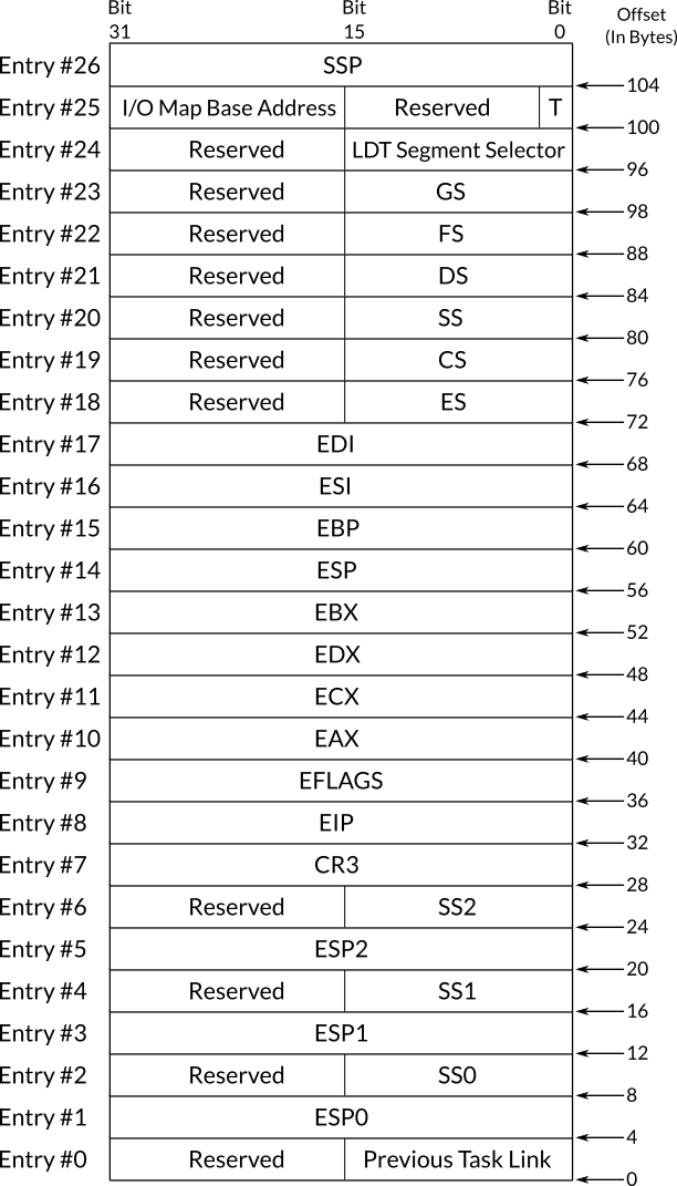
Figure 1: Figure 1: The Structure of Task-State Segment
Figure 1 shows the structure of a task-state segment, as you can see, most of the fields are values of registers while the others are out of our topic's range except for previous task link which will be covered in a moment. You can see that stack segment register and stack pointer register have four entries instead of one, SS, SS0, SS1 and SS2 for stack segment register. ESP, ESP0, ESP1 and ESP2 for stack pointer register. These fields point to the stack that should be used when the process is in a specific privilege level, for example, SS0:ESP0 will be used as the stack of the process when it switches to privilege level 0, when it switches back to privilege level 3 the stack SS:ESP will be used instead, and the same is applicable to the other similar fields. If we intend to implement software multitasking, the sole reason of defining at least one TSS is due to these fields, when a switch between privilege levels occurs, the processor needs a TSS to use these fields from it in order to switch between stacks. This is needed only when the system runs user-space code, that is, privilege level 3 code.
The structure of TSS descriptor in GDT table is same as the segment descriptor that we have already explained in chapter . The only difference is in the type field which has the static binary value 010B1 in TSS descriptor where B in this value is known as B flag, or busy flag which should be 1 when the process that this TSS descriptor represents is active and 0 when it is inactive.
4.4.2 Context Switching in x86
One way of switching from a process to another 6 in x86 hardware multitasking is to call or jump to TSS descriptor in GDT, assume that the system timer caused the call of the scheduler which selects process A as the next process to run, the scheduler can cause context switch by using the instructions call or jmp and the operand should be the segment selector of A's TSS descriptor. In this way, the processor is going to take a copy of currently running process (call it B) and store it in B's own TSS, then the values in A's TSS will be loaded into the processor registers and then execution of A begins.
Another way of context switching in x86 hardware multitasking is to call or jump to a task gate. In chapter , when we discussed the descriptors of IDT, we have said that one type of descriptor that can be defined is a task gate descriptor. This kind of descriptors is considered as a separated process by the processor, when we jump or call a task gate, the previously explained mechanism of task switching will be performed. Task gates can also be defined in GDT and LDT. In the IDT table of 539kernel we have chosen to not define the interrupts as task gates, we don't want to perform a context switch with each interrupt.
When a process is called instead of jumped to, eventually, it should return to the caller process by using the instruction iret, for the processor, to be able to decide which task is the caller, the previous task link field of the callee's TSS will be updated to contain the segment selector of the caller process. In this way, when iret instruction is executed, it will be easy to know to which process the processor should switch back to.
4.5 Process Management in 539kernel
The final result of this section is what I call version T of 539kernel which has a basic multitasking capability. The multitasking style that we are going to implement is time-sharing multitasking. Also, instead of depending on x86 features to implement multitasking in 539kernel, a software multitasking will be implemented. The final Makefile of version T is provided in the last subsection, however, if you wish to build and run the kernel incrementally after each change on the progenitor you can refer to that Makefile and add only the needed instructions to build the not ready yet version T that you are building. For example, as you will see in a moment new files screen.c and screen.h will be added in version T as a first increment, to run the kernel after adding them you need to add the command to compile this new file and link it with the previous files, you can find these commands in the last version of Makefile as we have said before.
Our first step of this implementation is to setup a valid task-state segment, while 539kernel implements a software multitasking, a valid TSS is needed. As we have said earlier, it will not be needed in our current stage but we will set it up anyway. Its need will show up when the kernel lets user-space software to run. After that, basic data structures for process table and process control block are implemented. These data structures and their usage will be as simple as possible since we don't have any mean for dynamic memory allocation, yet! After that, the scheduler can be implemented and system timer's interrupt can be used to enforce preemptive multitasking by calling the scheduler every period of time. The scheduler uses round-robin algorithm to choose the next process that will use the CPU time, and the context switching is performed after that. Finally, we are going to create a number of processes to make sure that everything works fine.
Before getting started in the plan that has been just described, we need to organize our code a little bit since it's going to be larger starting from this point. New two files should be created, screen.c and its header file screen.h. We move the printing functions that we have defined in the progenitor and their related global variables to screen.c and their prototypes should be in screen.h, so, we can include the latter in other C files when we need to use the printing functions. The following is the content of screen.h.
volatile unsigned char *video;

int nextTextPos;
int currLine;

void screen_init();
void print( char * );
void println();
void printi( int );
As you can see, a new function screen_init has been introduced while the others are same as the ones that we already wrote. The function screen_init will be called by the kernel once it starts running, the function initializes the values of the global variables video, nextTextPos and currLine. Its code is the following and it should be in screen.c, of course in the beginning of this file, screen.h should be included by using the line #include "screen.h".
void screen_init()
{
    video = 0xB8000;
    nextTextPos = 0;
    currLine = 0;
}
Nothing new in here, just some organizing. Now, the prototypes and implementations of the functions print, println and printi should be removed from main.c. Furthermore, the global variables video, nextTextPos and currLine should also be removed from main.c. Now, the file screen.h should be included in main.c and in the beginning of the function kernel_main the function screen_init should be called.
4.5.1 Initializing the Task-State Segment
Setting TSS up is too simple. First we know that the TSS itself is a region in the memory (since it is a segment), so, let's allocate this region of memory. The following should be added at end of starter.asm, even after including the files gdt.asm and idt.asm. In the following a label named tss is defined, and inside this region of memory, which its address is represented by the label tss, we put a doubleword of 0, recall that a word is 2 bytes while a double-word is 4 bytes. So, our TSS contains nothing but a bunch of zeros.
tss:
    dd 0
As you may recall, each TSS needs an entry in the GDT table, after defining this entry, the TSS's segment selector can be loaded into the task register. Then the processor is going to think that there is one process (one TSS entry in GDT) in the environment and it is the current process (The segment selector of this TSS is loaded into task register). Now, let's define the TSS entry in our GDT table. In the file gdt.asm we add the following entry at the end of the label gdt. You should not forget to modify the size of GDT under the label gdt_size_in_bytes under gdtr since the sixth entry has been added to the table.
tss_descriptor: dw tss + 3, tss, 0x8900, 0x0000Now, let's get back to starter.asm in order to load TSS' segment selector into the task register. In start routine and below the line call setup_interrupts we add the line call load_task_register which calls a new routine named load_task_register that loads the task register with the proper value. The following is the code of this routine that can be defined before the line bits 32 in starter.asm.
load_task_register:
    mov ax, 40d
    ltr ax

    ret
As you can see, it's too simple. The index of TSS descriptor in GDT is 40 = (entry 6 * 8 bytes) - 8 (since indexing starts from 0). So, the value 40 is moved to the register AX which will be used by the instruction ltr to load the value 40 into the task register.
4.5.2 The Data Structures of Processes
When we develop a user-space software and we don't know the size of the data that this software is going to store while it's running, we usually use dynamic memory allocation, that is, regions of memory are allocated at run-time in case we need to store more data that we didn't know that it will be needed to be stored. We have encountered the run-time stack previously, and you may recall that this region of memory is dedicated for local variables, parameters and some information that make function invocation possible.
The other region of a process is known as run-time heap, which is dedicated for the data that we decided to store in memory while the software is running. In C, for instance, the function malloc is used to allocate bytes from the run-time heap and maintains information about free and used space of the heap so in the next use of this function the allocation algorithm can decide which region should be allocated based on the required bytes to allocate.
This part that allocates memory dynamically (inside run-time heap) and manages the related stuff is known as memory allocator and one of well-known allocators is Doug Lea's memory allocator. For programming languages that run the program by using a virtual machine, like Java and C#, or by using interpreters like PHP and Python, they usually provide their users an automatic dynamic memory allocation instead of the manual memory allocation which is used by languages such as C, that is, the programmer of these languages don't need to explicitly call a function (such as malloc) to allocate memory in the heap at run-time, instead, the virtual machine or the interpreter allocates dynamic memory by itself and frees the region of the heap that are not used anymore through a mechanism known as garbage collection.
For those who don't know, in static memory allocation, the size of data and where will it be stored in the memory are known in compiling time, global variables and local variables are examples of objects that we use static memory allocation for them. In dynamic memory allocation, we cannot decide in compiling time the size of the data or whether it will be stored in the first place, these important information will only be known while the software is running, that is, in run-time. Due to that, we need to use dynamic memory allocation for them since this type of allocation doesn't require these information in the compiling time.
Processes table is an example of data structures (objects) that we can't know its size in compile-time and this information can be only decided while the kernel is running. Take your current operating system as an example, you can run any number of processes (to some limit of course) and all of them will have an entry in the processes table 7, maybe your system is running just two processes right now but you can run more and more without the need of recompiling the kernel in order to increase the size of processes table.
That's possible due to using dynamic memory allocation when a new process is created during run-time and that's by dynamically allocating a space in the run-time heap through the memory allocator for this the entry of this new process. When this process finishes its job (e.g. the user closes the application), the memory region that is used to store its entry in processes table is marked as free space so it can be used to store something else in the future, for example, the entry of another process.
In our current situation, we don't have any means of dynamic memory allocation in 539kernel, this topic will be covered when we start discussing memory management. Due to that, our current implementations of processes table and process control block are going to use static memory allocation through global variables. That of course, restricts us from creating a new process on-the-fly, that is, at run-time. But our current goal is to implement a basic multitasking that will be extended later. To start our implementation, we need to create new two files, process.c and its header file process.h. Any function or data structure that is related to processes should belong to these file.
4.5.2.1 Process Control Block
A process control block (PCB) is an entry in the processes table, it stores the information that are related to a specific process, the state and context of the process are examples of these information. In 539kernel, there are two possible states for a process, either a process is running or ready. When a context switch is needed to be performed, the context of the currently running process, which will be suspended, should be stored on its own PCB. Based on our previous discussions, the context of the process in 539kernel consists the values which were stored in the processor's registers before suspending the process.
Each process in 539kernel, as in most modern kernels, has a unique identifier known as process id or PID for short, this identifier is also stored in the PCB of the process. Now, let's define the general structure of PCB and its components in 539kernel. These definitions should reside in process.h.
typedef enum process_state { READY, RUNNING } process_state_t;

typedef struct process_context
{
    int eax, ecx, edx, ebx, esp, ebp, esi, edi, eip;
} process_context_t;

typedef struct process
{
    int pid;
    process_context_t context;
    process_state_t state;
    int *base_address;
} process_t;
As you can see, we start by a type known as process_state_t, any variable that has this type may have two possible values, READY or RUNNING, they are the two possible states of a process and this type will be used for the state field in PCB definition.
Next, the type process_context_t is defined. It represents the context of a process in 539kernel and you can see it is a C structure that intended to store a snapshot of x86 registers that can be used by a process.
Finally, the type process_t is defined which represents a process control block, that is, an entry in the processes table. A variable of type process_t represents one process in 539kernel environment. Each process has a pid which is its unique identifier. A context which is the snapshot of the environment before suspending the process. A state which indicates whether a process is READY to run or currently RUNNING. And finally, a base_address which is the memory address of the process' code starting point (think of main() in C), that is, when the kernel intend to run a process for the first time, it should jump to the base_address, in other words, set EIP to base_address.
4.5.2.2 Processes Table
In the current case, as we mentioned earlier, we are going to depend on static memory allocation since we don't have any way to employ dynamic memory allocation. Due to that, our processes table will be too simple, it is an array of type process_t. Usually, more advanced data structure is used for the processes list based on the requirements which are decided by the kernelist, linked list data structure is a well-known choice. The following definition should reside in process.h. Currently, the maximum size of 539kernel processes table is 15 processes, feel free to increase it but don't forget, it will, still, be a static size.
process_t *processes[ 15 ];4.5.3 Process Creation
Now, we are ready to write the function that creates a new process in 539kernel. Before getting started in implementing the required functions, we need to define their prototypes and some auxiliary global variables in process.h.
int processes_count, curr_pid;

void process_init();
void process_create( int *, process_t * );
The first global variable processes_count represents the current number of processes in the environment, this value will become handy when we write the code of the scheduler which uses round-robin algorithm, simply, whenever a process is created in 539kernel, the value of this variable is increased and since deleting a process will not be implemented for the sake of simplicity, the value of this variable will not be decreased anywhere in the current code of 539kernel.
The global variable curr_pid contains the next available process identifier that can be used for the next process that will be created. The current value of this variable is used when creating a new process and its value is increased by one after completing the creation.
The function process_init is called when the kernel starts, and it initializes the process management subsystem by just initializing the two global variables that we mentioned.
The function process_create is the one that creates a new process in 539kernel, that is, it is equivalent to fork in Unix systems. As you can see, it takes two parameters, the first one is a pointer to the base address of the process, that is, the starting point of the process' code. The second parameter is a pointer to the process control block, as we have said, currently, we use static memory allocation, therefore, each new PCB will be either stored in the memory as a local or global variables, so, for now, the caller is responsible for allocating a static memory for the PCB and passing its memory address in the second parameter. In the normal situation, the memory of a PCB is allocated dynamically by the creation function itself, but that's a story for another chapter. The following is the content of process.c as we have described.
#include "process.h"

void process_init()
{
    processes_count = 0;
    curr_pid = 0;
}

void process_create( int *base_address, process_t *process )
{
    process->pid = curr_pid++;

    process->context.eax = 0;
    process->context.ecx = 0;
    process->context.edx = 0;
    process->context.ebx = 0;
    process->context.esp = 0;
    process->context.ebp = 0;
    process->context.esi = 0;
    process->context.edi = 0;
    process->context.eip = base_address;

    process->state = READY;
    process->base_address = base_address;

    processes[ process->pid ] = process;

    processes_count++;
}
In process_create, a new process identifier is assigned to the new process. Then the context is initialized, this structure will be used later in context switching, either by copying the values from the processor to the structure or vice versa. Since the new process has not been run yet, hence, it didn't set any value to the registers, then we initialize all general purpose registers with 0, later on, when this process runs and the scheduler decides to suspend it, the values that this process wrote on the real registers will be copied in here. The structure field of program counter EIP is initialized with the starting point of the process' code, in this way we can make sure that when the scheduler decides to run this process, it loads the correct value to the register EIP.
After initializing the context, the state of the process is set as READY to run and the base address of the process is stored in a separate field. Then, the freshly-created PCB is added to the processes list and finally the number of processes in the system is increased by one.
That' all we need for now to implement multitasking, in real cases, there will be usually more process states such as waiting, the data structures are allocated dynamically to make it possible to create virtually any number of processes, the PCB may contains more fields and more functions to manipulate processes table (e.g. delete process) are implemented. However, our current implementation, though too simple, it is enough as a working foundation. Now, in main.c, the header file process.h is needed to be included, and the function process_init should be called in the beginning of the kernel, after the line screen_init();.
4.5.4 The Scheduler
Right now, we have all needed components to implement the core of multitasking, that is, the scheduler. As mentioned multiple times before, round-robin algorithm is used for 539kernel's scheduler.
Let's present two definitions to make our next discussion more clear. The term current process means the process that is using the processor right now, at some point of time, the system timer emits an interrupt which suspends the current process and calls the kernel to handle the interrupt, In this case the kernel is going to call the scheduler, at this point of time, we keep the same term for the process which was running right before calling the kernel to handle the interrupt, we call it the current process. By using some algorithm, the scheduler chooses the next process, that is, the process that will run after the scheduler finishes its work and the kernel returns the processor to the processes. After choosing the next process, performing the context switching and jumping to the process code, this chosen process will be the current process instead of the suspended one, and it will be the current process until the next run of the scheduler and so on.
Now, we are ready to implement the scheduler, let's create a new file scheduler.c and its header file scheduler.h for the new code. The following is the content of the header file.
#include "process.h"

int next_sch_pid, curr_sch_pid;

process_t *next_process;

void scheduler_init();
process_t *get_next_process();
void scheduler( int, int, int, int, int, int, int, int, int );
void run_next_process();
First, process.h is included since we need to use the structure process_t in the code of the scheduler. Then three global variables are defined, the global variable next_sch_pid stores the PID of the next process that will run after next system timer interrupt, while curr_sch_pid stores the PID of the current process. The global variable next_process stores a reference to the PCB of the next process, this variable will be useful when we want to move the control of the processor from the kernel to the next process which is the job of the function run_next_process.
The function scheduler_init sets the initial values of the global variables, same as process_init, it will be called when the kernel starts.
The core function is scheduler which represents 539kernel's scheduler, this function will be called when the system timer emits its interrupt. It chooses the next process to run with the help of the function get_next_process, performs context switching by copying the context of the current process from the registers to the memory and copying the context of the next process from the memory to the registers. Finally, it returns and run_next_process is called in order to jump the the next process' code. In scheduler.c, the file scheduler.h should be included to make sure that everything works fine. The following is the implementation of scheduler_init.
void scheduler_init()
{
    next_sch_pid = 0;
    curr_sch_pid = 0;
}
It's too simple function that initializes the values of the global variables by setting the PID 0 to both of them, so the first process that will be scheduled by 539kernel is the process with PID 0.
Next, is the definition of get_next_process which implements round-robin algorithm, it returns the PCB of the process that should run right now and prepare the value of next_sch_pid for the next context switching by using round-robin policy.
process_t *get_next_process()
{
    process_t *next_process = processes[ next_sch_pid ];

    curr_sch_pid = next_sch_pid;
    next_sch_pid++;
    next_sch_pid = next_sch_pid % processes_count;

    return next_process;
}
Too simple, right! 8 If you haven't encountered the symbol % previously, it represents an operation called modulo which gives the remainder of division operation, for example, 4 % 2 = 0 because the reminder of dividing 4 on 2 is 0, but 5 % 2 = 1 because 5 / 2 = 2 and remainder is 1, so, 5 = ( 2 * 2 ) + 1 (the remainder).
In modulo operation, any value n that has the same position of 2 in the previous two examples is known as modulus. For instance, the modulus in 5 % 3 is 3 and the modulus in 9 % 10 is 10 and so on. In some other places, the symbol mod is used to represent modulo operation instead of %.
The interesting thing about modulo that its result value is always between the range 0 and n - 1 given that n is the modulus. For example, let the modulus be 2, and we perform the following modulo operation x % 2 where x can be any number, the possible result values of this operation are only 0 or 1. Using this example with different values of x gives us the following results, 0 % 2 = 0, 1 % 2 = 1, 2 % 2 = 0, 3 % 2 = 1, 4 % 2 = 0, 5 % 2 = 1, 6 % 2 = 0 and so on to infinity!
As you can see, modulo gives us a cycle that starts from 0 and ends at some value that is related to the modulus and starts all over again with the same cycle given an ordered sequence of values for x, sometimes the analog clock is used as metaphor to describe the modulo operation. However, in mathematics a topic known as modular arithmetic is dedicated to the modulo operation. You may noticed that modulo operation can be handy to implement round-robin algorithm.
Let's get back to the function get_next_process which chooses the next process to run in a round-robin fashion. As you can see, it assumes that the PID of the next process can be found directly in next_sch_pid. By using this assumption it fetches the PCB of this process to return it later to the caller. After that, the value of curr_sch_pid is updated to indicate that, right now, the current process is the one that we just selected to run next. The next two lines are the core of the operation of choosing the next process to run, it prepares which process will run when next system timer interrupt occurs.
Assume that the total number of processes in the system is 4, that is, the value of processes_count is 4, and assume that the process that will run in the current system timer interrupt has the PID 3, that is next_sch_pid = 3, PIDs in 539kernel start from 0, that means there is no process with PID 4 in our example and process 3 is the last one.
In line next_sch_pid++ the value of the variable will be 4, and as we mentioned, the last process is 3 and there is no such process 4, that means we should start over the list of processes and runs process 0 in the next cycle, we can do that simply by using modulo on the new value of next_sch_pid with the modulus 4 which is the number of processes in the system process_count, so, next_sch_pid = 4 % 4 = 0. In the next cycle, process 0 will be chosen to run, the value of next_sch_pid will be updated to 1 and since it is lesser than process_count it will be kept for the next cycle. After that, process 1 will run and the next to run will be 2. Then process 2 will run and next to run is 3. Finally, the same situation that we started our explanation with occurs again and process 0 is chosen to run next. The following is the code of the function scheduler.
void scheduler( int eip, int edi, int esi, int ebp, int esp, int ebx, int edx, int ecx, int eax )
{
    process_t *curr_process;

    // ... //

    // PART 1

    curr_process = processes[ curr_sch_pid ];
    next_process = get_next_process();

    // ... //

    // PART 2

    if ( curr_process->state == RUNNING )
    {
        curr_process->context.eax = eax;
        curr_process->context.ecx = ecx;
        curr_process->context.edx = edx;
        curr_process->context.ebx = ebx;
        curr_process->context.esp = esp;
        curr_process->context.ebp = ebp;
        curr_process->context.esi = esi;
        curr_process->context.edi = edi;
        curr_process->context.eip = eip;
    }

    curr_process->state = READY;

    // ... //

    // PART 3

    asm( "  mov %0, %%eax;  \
            mov %0, %%ecx;  \
            mov %0, %%edx;  \
            mov %0, %%ebx;  \
            mov %0, %%esi;  \
            mov %0, %%edi;"
            : : "r" ( next_process->context.eax ), "r" ( next_process->context.ecx ), "r" ( next_process->context.edx ), "r" ( next_process->context.ebx ),
                "r" ( next_process->context.esi ), "r" ( next_process->context.edi ) );

    next_process->state = RUNNING;
}
I've commented the code to divide it into three parts for the sake of simplicity in our discussion. The first part is too simple, the variable curr_process is assigned to a reference to the current process which has been suspended due to the system timer interrupt, this will become handy in part 2 of scheduler's code, we get the reference to the current process before calling the function get_next_process because, as you know, this function changes the variable of current process' PID (curr_sch_pid) from the suspended one to the next one 9. After that, the function get_next_process is called to obtain the PCB of the process that will run this time, that is, the next process.
As you can see, scheduler receives nine parameters, each one of them has a name same as one of the processor's registers. We can tell from these parameters that the function scheduler receives the context of the current process before being suspended due to system timer's interrupt. For example, assume that process 0 was running, after the quantum finished the scheduler is called, which decides that process 1 should run next. In this case, the parameters that have been passed to the scheduler represent the context of process 0, that is, the value of the parameter EAX will be same as the value of the register EAX that process 0 set at some point of time before being suspended. How did we get these values and pass them as parameters to scheduler? This will be discussed later.
In part 2 of scheduler's code, the context of the suspended process, which curr_process represents it right now, is copied from the processor into its own PCB by using the passed parameter. Storing current process' context into its PCB is simple as you can see, we just store the passed values in the fields of the current process structure. These values will be used later when we decide to run the same process. Also, we need to make sure that the current process is really running by checking its state before copying the context from the processor to the PCB. At the end, the state of the current process is switched from RUNNING to READY.
Part 3 performs the opposite of part 2, it uses the PCB of the next process to retrieve its context before the last suspension, then this context will be copied to the registers of the processor. Of course, not all of them are being copied to the processor, for example, the program counter EIP cannot be written to directly, we will see later how to deal with it. Also, the registers that are related to the stack, ESP and EBP were skipped in purpose. As a last step, the state of the next process is changed from READY to RUNNING. The following is the code of run_next_process which is last function remains in scheduler.c.
void run_next_process()
{
    asm( "  sti;            \
            jmp *%0" : : "r" ( next_process->context.eip ) );
}
It is a simple function that executes two assembly instructions. First it enables the interrupts via the instruction sti, then it jumps to the memory address which is stored in the EIP of next process' PCB. The purpose of this function will be discussed after a short time.
To make everything runs properly, scheduler.h need to be included in main.c, note that, when we include scheduler.h, the line which includes process.h should be remove since scheduler.h already includes it. After that, the function scheduler_init should be called when initializing the kernel, say after the line which calls process_init.
4.5.4.1 Calling the Scheduler
"So, how the scheduler is being called" you may ask. The answer to this question has been mentioned multiple times before. When the system timer decides that it is the time to interrupt the processor, the interrupt 32 is being fired, this point of time is when the scheduler is being called. In each period of time the scheduler will be called to schedule another process and gives it CPU time.
In this part, we are going to write a special interrupt handler for interrupt 32 that calls 539kernel's scheduler. First we need to add the following lines in the beginning of starter.asm 10 after extern interrupt_handler.
extern scheduler
extern run_next_process
As you may guessed, the purpose of these two lines is to make the functions scheduler and run_next_process of scheduler.c usable by the assembly code of starter.asm. Now, we can get started to implement the code of interrupt 32's handler which calls the scheduler with the needed parameters. In the file idt.asm the old code of the routine isr_32 should be changed to the following.
isr_32:
    ; Part 1

    cli ; Step 1

    pusha ; Step 2

    ; Step 3
    mov eax, [esp + 32]
    push eax

    call scheduler ; Step 4

    ; ... ;

    ; Part 2

    ; Step 5
    mov al, 0x20
    out 0x20, al

    ; Step 6
    add esp, 40d
    push run_next_process

    iret ; Step 7
There are two major parts in this code, the first one is the code which will be executed before calling the scheduler, that is, the one before the line call scheduler. The second one is the code which will be executed after the scheduler returns.
The first step of part one disables the interrupts via the instruction cli. When we are handling an interrupt, it is better to not receive any other interrupt, if we don't disable interrupts here, while handling a system timer interrupt, another system timer interrupt can occur even before calling the scheduler in the first time, you may imagine the mess that can be as a result of that.
Before explaining the steps two and three of this routine, we need to answer a vital question: When this interrupt handler is called, what the context of the processor will be? The answer is, the context of the suspended process, that is, the process that was running before the system timer emitted the interrupt. That means all values that were stored by the suspended process on the general purpose registers will be there when isr_32 starts executing and we can be sure that the processor did not change any of these values during suspending the process and calling the handler of the interrupt, what gives us this assurance is the fact that we have defined all ISRs gate descriptors as interrupt gates in the IDT table, if we have defined them as task gates, the context of the suspended process will not be available directly on processor's registers. Defining an ISR descriptor as an interrupt gate makes the processor to call this ISR as a normal routine by following the calling convention. It's important to remember that when we discuss obtaining the value of EIP of the suspended process later on in this section.
By knowing that the context of suspended process is reachable via the registers (e.g EAX) we can store a copy of them in the stack, this snapshot will be useful when the scheduler needs to copy the context of the suspended process to the memory as we have seen, also, pushing them into stack gives as two more benefits. First we can start to use the registers in the current code as we like without the fear of losing the suspended process context, it is already stored in the stack and we can refer to it anytime we need it. Second, according to the calling convention that we have discussed in chapter these pushed values can be considered as parameters for a function that will be called and that's exactly how we pass the context of suspended process to the function scheduler as parameters, simply by pushing the values of general purpose registers into the stack.
Now, instead of writing 8 push instructions to push these values into the stack, for example push eax and so on, there is an x86 instruction named pusha which pushes the current values of all general purpose registers into the stack, that exactly what happens in the second step of isr_32 in order to send them as parameters to the function scheduler. The reverse operation of pusha can be performed by the instruction popa, that is, the values on the stack will be loaded into the registers.
The instruction pusha pushes the values of the registers in the following order: EAX, ECX, EDX, EBX, ESP, EBP, ESI and EDI. Based on the calling convention they will be received as parameters in the reversed order, that is, the first pushed values will be the last one to receive, so, the parameter that contains the value of EDI will be before ESI in the parameters list and so on, you can see that in an obvious way in the parameters list of the function scheduler.
The only missing piece now is the value of the instruction pointer EIP, the third step of isr_32 obtains this value. As you know, it is too important to store the last EIP value of the suspended process, we need to know where did the execution of the suspended process code stop so we can resume its work later from the same point, and this information can be known through EIP.
Not like the general purpose registers, the value of EIP will not be pushed into the stack by the instruction pusha, furthermore, the current EIP is by no means a pointer to where the suspended process stopped, as you know, the current value of EIP is a pointer to the current instruction which is being executed right now, that is, one of isr_32 instructions. So, the question is, where can we find the value of EIP which was there just before the suspended process has been suspended? The answer again can be found in the calling convention.

Figure 2: Figure 2: The Stack After Executing the Instruction pusha
Let's assume that a process named A was running and a system timer interrupt occurred which caused process A to suspend and isr_32 to start, as we have mentioned earlier, isr_32 will be called as a normal routine and the calling convention will be followed by the processor. Figure 2 shows the stack at the time after executing pusha in isr_32. As you can see, the context of process A is on the stack, for example, to reach the value of ESI which was stored right before the process A has been suspended, we can do that by referring to the memory address ESP + 4 11, since the current ESP stores the memory address of the top of the stack, the size of the value of EDI (and all other registers) is 4 bytes and the value of ESI is next to the top of the stack.
The same technique can be used with any value in stack. As you may have noticed in the figure, that the return address to where process A suspended is stored in the stack, and that's due to the calling convention which requires the return address of the caller to be stored in the stack so we can return to it, as you can see, here, the process A was considered as the caller and isr_32 as the callee. So, to obtain the value of process A's return address, we can do that simply by reading the value in esp + 32, and that exactly what we have done in the third step of isr_32 code, we first read this value and then push it into the stack so the function scheduler can receive it as the first parameter.
The fourth and fifth steps are simple, in the fourth step we call the function scheduler which we have already discussed, after the function scheduler returns, we need to tell PIC that we finished the handling of an IRQ by sending end of interrupt command to the PIC and that's what is performed in the fifth step, we have already discussed sending end of interrupt command to PIC in chapter .
The final thing to do after choosing the next process and performing the context switching is to give a CPU time for the code of the next process. This is usually performed by jumping to the memory address in which the selected process where suspended. There are multiple ways to do that, the way which we have used in 539kernel is to exploit the calling convention, again.
As we have mentioned before, the return address to the caller is stored in the stack, in our previous example, the return address to process A was stored in the stack right before the values of process A context which have been pushed by the instruction pusha. When a routine returns by using the instruction ret or iret, this address will be jumped to, we exploit this fact to make the next process runs after isr_32 finishes instead of process A, this is too simple to be done, the return address of process A should be removed from the stack and in its position in the stack the resume point of the next process is pushed, that's what we do in the sixth step of isr_32.
First we remove all values that we have pushed on the stack while running isr_32, this is performed by just adding 40 to the current value of ESP, we have already discussed this method of removing values from the stack, why adding 40? You may ask. The number of values that have been pushed by the instruction pusha is 8 values, each one of them of size 4 bytes (32-bit), that means the total size of them is 4 * 8 = 32. Also, we have pushed the value of EIP which also has the size of 4 bytes, so, until now the total size of pushed items in isr_32 is 32 + 4 = 36 and these are all what we have pushed in purpose, we also need to remove the return address which has been pushed into the stack before calling isr_32, the size of memory addresses in 32-bit architecture is 4 bytes (32-bit), that means 36 + 4 = 40 bytes should be removed from the stack to ensure that we remove all pushed values with the return address or process A.
After that, we simply push the memory address of the function run_next_process. In the seventh step, the routine isr_32 returns indicating that handling an interrupt has been completed, but instead of returning to the suspended code before calling the interrupt handler, the code of the function run_next_process will be called, which is, as we have seen, enables the interrupts again and jumps to the resume point of the next process. In this way, we have got a basic multitasking!
4.5.5 Running Processes
In our current environment, we will not be able to test our process management by using the normal ways, I mean, we can't run a user-space software to check if its process has been created and being scheduled or not. Instead, we are going to create a number of processes by creating their PCBs via process_create function, and their code will be defined as functions in our kernel, the memory address of these functions will be considered as the starting point of the process. Our goal of doing that is just to test that our code of process management is running well. All code of this section will be in main.c unless otherwise is mentioned. First, we define prototypes for four functions, each one of them represents a separate process, imaging them as a normal use-space software. These prototypes should be defined before kernel_main.
void processA();
void processB();
void processC();
void processD();
Inside kernel_main, we define four local variables. Each one of them represents the PCB of one process.
process_t p1, p2, p3, p4;Before the infinite loop of kernel_main we create the four processes in the system by using the function process_create as the following.
    process_create( &processA, &p1 );
    process_create( &processB, &p2 );
    process_create( &processC, &p3 );
    process_create( &processD, &p4 );
The code of the processes is the following.
void processA()
{
    print( "Process A," );

    while ( 1 )
        asm( "mov $5390, %eax" );
}

void processB()
{
    print( "Process B," );

    while ( 1 )
        asm( "mov $5391, %eax" );
}

void processC()
{
    print( "Process C," );

    while ( 1 )
        asm( "mov $5392, %eax" );
}

void processD()
{
    print( "Process D," );

    while ( 1 )
        asm( "mov $5393, %eax" );
}
Each process starts by printing its name, then, an infinite loop starts which keeps setting a specific value in the register EAX. To check whether multitasking is working fine, we can add the following lines the beginning of the function scheduler in scheduler.c.
    print( " EAX = " );
    printi( eax );
Each time the scheduler starts, it prints the value of EAX of the suspended process. When we run the kernel, each process is going to start by printing its name and before a process starts executing the value of EAX of the previous process will be shown. Therefore, you will see a bunch of following texts EAX = 5390, EAX = 5391, EAX = 5392 and EAX = 5393 keep showing on the screen which indicates that the process, A for example in case EAX = 5390 is shown, was running and it has been suspended now to run the next one and so on.
4.5.6 Finishing up Version T
And we have got version T of 539kernel which provides us a basic process management subsystem. The last piece to be presented is the Makefile to compile the whole code.
ASM = nasm
CC = gcc
BOOTSTRAP_FILE = bootstrap.asm
INIT_KERNEL_FILES = starter.asm
KERNEL_FILES = main.c
KERNEL_FLAGS = -Wall -m32 -c -ffreestanding -fno-asynchronous-unwind-tables -fno-pie
KERNEL_OBJECT = -o kernel.elf

build: $(BOOTSTRAP_FILE) $(KERNEL_FILE)
    $(ASM) -f bin $(BOOTSTRAP_FILE) -o bootstrap.o
    $(ASM) -f elf32 $(INIT_KERNEL_FILES) -o starter.o
    $(CC) $(KERNEL_FLAGS) $(KERNEL_FILES) $(KERNEL_OBJECT)
    $(CC) $(KERNEL_FLAGS) screen.c -o screen.elf
    $(CC) $(KERNEL_FLAGS) process.c -o process.elf
    $(CC) $(KERNEL_FLAGS) scheduler.c -o scheduler.elf
    ld -melf_i386 -Tlinker.ld starter.o kernel.elf screen.elf process.elf scheduler.elf -o 539kernel.elf
    objcopy -O binary 539kernel.elf 539kernel.bin
    dd if=bootstrap.o of=kernel.img
    dd seek=1 conv=sync if=539kernel.bin of=kernel.img bs=512 count=8
    dd seek=9 conv=sync if=/dev/zero of=kernel.img bs=512 count=2046
    qemu-system-x86_64 -s kernel.img
Nothing new in here but compiling the new C files that we have added to 539kernel.
We mean static data here, which are contained in the binary file of the software. While the data that are generated by the running process are not loaded from the binary file, instead they are created while the code is running (e.g. local variables in the stack).↩
Remember the job of a kernelist!↩
You may ask who would use cooperative multitasking and give this big trust to the code of the software! In fact, the versions of Windows before 95 used this style of multitasking, also, Classic Mac OS used it. Why? You may ask, I don't know exactly, but what I know for sure is that humanity is in a learning process!↩
In x86, the term task is used instead of process.↩
In chapter we have seen that there are two types of segments in x86, application segments such as code, data and stack segment. And system segments and they are
LDTandTSS.↩In x86, context switch is known as task switch.↩
We already know that keeping an entry of a process in the processes table is important for the scheduling process and other related processes stuff.↩
Could be simpler, but the readability is more important here.↩
And that's why the global variables are considered evil.↩
I'm about to regret that I called this part of the kernel the starter! obviously it's more than that!↩
If a new stack frame is created once
isr_32starts then alsoEBPcan be used as a base address but with different offset than4of course as we have explained earlier in chapter . I didn't initialize a new stack frame here and in all other places to get a shorter code.↩