Chapter 3. The Progenitor of 539kernel
3.1 Introduction
Till the point, we have created a bootloader for 539kernel that loads a simple assembly kernel from the disk and gives it the control. Furthermore, we have gained enough knowledge of x86 architecture's basics to write the progenitor of 539kernel which is, as we have said, a 32-bit x86 kernel that runs in protected-mode. In x86, to be able to switch from real-mode to protected-mode, the global descriptor table (GDT) should be initialized and loaded first. After entering the protected mode, the processor will be able to run 32-bit code which gives us the chance to write the rest of kernel's code in C and use some well-known C compiler (We are going to use GNU GCC in this book) to compile the kernel's code to 32-bit binary file. When our code runs in protected-mode, the ability of reaching BIOS services will be lost which means that printing text on the screen by using BIOS service will not be available for us, although the part of printing to the screen is not an essential part of a kernel, but we need it to check if the C code is really running and that's by printing some text once the C code gains the control of the system. Instead of using BIOS to print texts, we need to use the video memory to achieve this goal in protected mode which introduces us to a graphics standard known as video graphics array (VGA).
The final output of this chapter will be the progenitor of 539kernel which has a bootloader that loads the kernel which contains two parts, the first part is called starter which is written in assembly and will be represented by a file called starter.asm, this part initializes and loads the GDT table, then it is going to change the operating mode of the processor from real-mode to protected-mode and finally it is going to prepare the environment for the C code of the kernel which is the second part (we are going to call this part the main kernel code or main kernel in short) that will be represented by a file called main.c it is going to gain the control from the starter after the latter finishes its work. In this early stage, the C code will only contains an implementation for print function and it is going to print some text on the screen, in the later stages, this part will contain the main code of 539kernel.
3.2 The Basic Code of The Progenitor
In this section we are going to start writing the most of 539kernel's progenitor code but one part which is related to the interrupts that will be examined in another section in this chapter. To be able to compile and run the code that we write in this section you need to update the Makefile of 539kernel, the changes of Makefile also will be examined in another section in this chapter. The following is the Makefile which presumes that both starter.asm and main.c are available.
ASM = nasm
CC = gcc
BOOTSTRAP_FILE = bootstrap.asm
INIT_KERNEL_FILES = starter.asm
KERNEL_FILES = main.c
KERNEL_FLAGS = -Wall -m32 -c -ffreestanding -fno-asynchronous-unwind-tables -fno-pie
KERNEL_OBJECT = -o kernel.elf

build: $(BOOTSTRAP_FILE) $(KERNEL_FILE)
    $(ASM) -f bin $(BOOTSTRAP_FILE) -o bootstrap.o
    $(ASM) -f elf32 $(INIT_KERNEL_FILES) -o starter.o
    $(CC) $(KERNEL_FLAGS) $(KERNEL_FILES) $(KERNEL_OBJECT)
    ld -melf_i386 -Tlinker.ld starter.o kernel.elf -o 539kernel.elf
    objcopy -O binary 539kernel.elf 539kernel.bin
    dd if=bootstrap.o of=kernel.img
    dd seek=1 conv=sync if=539kernel.bin of=kernel.img bs=512 count=5
    dd seek=6 conv=sync if=/dev/zero of=kernel.img bs=512 count=2046
    qemu-system-x86_64 -s kernel.img
As you can see, a linker ld is now used to group the object files which has been generated from the compiler and the assembler. The linker needs a script which tells it how to organize the content of the binary file 539kernel.elf that will be generated by the linker. The name of the file should be linker.ld as it's shown in the arguments of the command. The following is the content of this file 1.
SECTIONS
{
  .text 0x09000 :
  {
    code = .; _code = .; __code = .;
    *(.text)
  }

  .data :
  {
     data = .; _data = .; __data = .;
     *(.data)
     *(.rodata)
  }

  .bss :
  {
    bss = .; _bss = .; __bss = .;
    *(.bss)
  }

  end = .; _end = .; __end = .;
}
The bootloader also should be modified to make the progenitor code works. In the previous version of the bootloader, we were loading only one sector from the disk (remember, the size of a sector is 512 bytes) to memory, and that was more than enough for simple code such as simple_kernel.asm of chapter . In most practical cases, the size of the kernel will be more than one sector and the 539kernel's progenitor is not an exception, therefore, the bootloader should load more than one sector in order to load the whole code of the kernel. First we need to add two new data labels in the bootloader, say below the definition of the label load_error_string, as the following.
number_of_sectors_to_load   db  15d
curr_sector_to_load         db  2d
The first one, as it is obvious from its name, indicates the number of sectors that we would like our bootloader to load from the disk, the current value is 15d, which means 7.5KB from the disk will be loaded to the memory, if kernel's binary size becomes larger than 7.5KB we can simply modify the value of this label to increase the number of sectors to load.
The second label indicates the sector's number that we are going to load now, as you know, sector 1 of the disk contains the bootloader (if sector numbering starts from 1), and based on our arrangement in Makefile of 539kernel, the code of the kernel will be there starting from sector 2 of the disk, therefore, the initial value of the label curr_sector_to_load is 2. The modified version of load_kernel_from_disk which loads more than one sector is the following.
load_kernel_from_disk:
    mov ax, [curr_sector_to_load]
    sub ax, 2
    mov bx, 512d
    mul bx
    mov bx, ax

    mov ax, 0900h
    mov es, ax

    mov ah, 02h
    mov al, 1h
    mov ch, 0h
    mov cl, [curr_sector_to_load]
    mov dh, 0h
    mov dl, 80h
    int 13h

    jc kernel_load_error

    sub byte [number_of_sectors_to_load], 1
    add byte [curr_sector_to_load], 1
    cmp byte [number_of_sectors_to_load], 0

    jne load_kernel_from_disk

    ret
The first difference in this new version of load_kernel_from_disk is the first 5 lines of this routine. As you may recall, the BIOS service 13h:02h loads the required sector into the memory address es:bx, so, the value 0900h which has been set to es in the code above will be the starting memory address of the kernel. In the previous version of the bootloader it was enough the set 0 to bx since we were loading only one sector, that means the code will reside from offset 0 to offset 511 of the segment. Now we are loading more than one sector by executing load_kernel_from_disk multiple times (number_of_sectors_to_load times) with different curr_sector_to_load each time, so, if we keep the value of bx fixed to 0, each sector will overwrite the previously loaded sector and only the last sector of the kernel will be there in memory, which is, of course, not what we want. The first five lines of load_kernel_from_disk ensures that each sector is loaded in the correct memory location, the first sector is loaded starting from offset 0 ((2 - 2) * 512 = 0), the second sector is loaded starting from offset 512 ((3 - 2) * 512 = 512) and the third sector is loaded starting offset 1024 ((4 - 2) * 512 = 1024).
The second change of the routine is the value that we set to the register cl. For BIOS's 13h:02h the value of this register is the sector number that we would like to load the data from. In the new version, this value depends on curr_sector_to_load which starts with 2 and increases by 1 after each sector being loaded. The last 4 lines before ret ensures that the value of curr_sector_to_load is being increased to load the next sector from disk in the next iteration of the routine, the value of number_of_sectors_to_load is decreased by 1 after loading each sector and finally the new value of number_of_sectors_to_load is compared with 0, when it is the case then the routine load_kernel_from_disk will return, otherwise, the routine will be called again with the new values for both curr_sector_to_load, number_of_sectors_to_load to load a new sector and so on.
3.2.1 Writing the Starter
The starter is the first part of 539kernel that runs right after the bootloader which means that the starter runs in 16-bit real-mode environment, exactly same as the bootloader, and due to that we are going to write the starter by using assembly language instead of C and that's because most modern C compilers don't support 16-bit code. Furthermore, when a specific low-level instruction is needed (e.g. lgdt), there is no way to call this instruction in native C, instead, assembly language should be used.
The main job of the starter is to prepare the proper environment for the main kernel to run in. to do that the starter switches the current operating mode from the real-mode to protected-mode which, as we have said earlier, gives us the chance to run 32-bit code. Before switching to protected-mode, the starter needs to initialize and load the GDT table and set the interrupts up, furthermore, to be able to use the video memory correctly in protected-mode a proper video mode should be set, we are going to discuss the matter of video in more details later in this chapter. After finishing these tasks, the starter will be able to switch to protected-mode and gives the control to the main kernel. Let's start with the prologue of the starter's code which reflects the steps that we have just described.
bits 16
extern kernel_main

start:
    mov ax, cs
    mov ds, ax

    call load_gdt
    call init_video_mode
    call enter_protected_mode
    call setup_interrupts

    call 08h:start_kernel
The code of the starter begins from the label start, from now on I'm going to use the term routine for any callable assembly label 2. You should be familiar with the most of this code, as you can see, the routine start begins by setting the proper memory address of data segment depending on the value of the code segment register cs 3 which is going to be same as the beginning of the starter's code. After that, the four steps that we have described are divided into four routines that we are going to write during this chapter, these routines are going to be called sequentially. Finally, the starter preforms a far jump to the code of the main kernel. But before examining the details of those steps let's stop on the first two line of this code that could be new to you.
bits 16
extern kernel_main
The first line uses the directive bits which tells NASM that the code that follows this line is a 16-bit code, remember, we are in a 16-bit real-mode environment, so our code should be a 16-bit code. You may wonder, why didn't we use this directive in the bootloader's code? The main reason for that is how NASM works, when you tell NASM to generate the output in a flat binary format 4, it is going to consider the code as a 16-bit code by default unless you use bits directive to tell NASM otherwise, for example bits 32 for 32-bit code or bits 64 for 64-bit code. But in the case of the starter, it is required from NASM to assemble it as ELF32 instead of flat binary, therefore, the 16-bit code should be marked from NASM to assemble it as 16-bit code and not 32-bit code which is the default for ELF32.
The second line uses the directive extern which tells NASM that there is a symbol 5 which is external and not defined in any place in the current code (for example, as a label) that you are assembling, so, whenever the code that you are assembling uses this symbol, don't panic, and continue your job, and the address of this symbol will be figured out later by the linker. In our situation, the symbol kernel_main is the name of a function that will be defined as a C code in the main kernel code and it is the starting point of the main kernel.
As I've said earlier, the stuff that are related to interrupts will be examined in another section of this chapter. To get a working progenitor we are going to define the routine setup_interrupts as an empty routine temporarily until we reach the interrupts section. Its code will be the following.
setup_interrupts:
    ret
3.2.1.1 Entering Protected-Mode
The code of load_gdt routine is the following.
load_gdt:
    cli
    lgdt [gdtr - start]

    ret
According to Intel's x86 manual, it is recommended to disable the interrupts before starting the process of switching to protected-mode, so, the first step of load_gdt routine is to disable the interrupts by using the instruction cli 6.
The second step of load_gdt is setting the value of GDTR register. In the operand of lgdt in this line you can see two symbols, gdtr and start. Both of these symbols are labels in the starter code, we have already defined start as a label for the main routine of the starter, but the label gdtr is a one that we are going to define later. What you need to know right now about this label is that it contains the value that we would like to load into the register GDTR, that is, it contains the memory address of the 539kernel's GDT table and the size of the table.
From our previous discussions, you know that when we mention any label through the assembly code, NASM will substitute it by the memory address of this label, so, what is going on with the operand [gdtr - start] of lgdt? And why do we need to subtract the memory address of the label start from the memory address of label gdtr?
First we need to understand the meaning of the brackets [] in NASM. Those brackets are used to refer to the content of a memory address inside the brackets, for example, assume we have a label named foo and we store the value bar in this label, inn the same way of the labels title_string and message_string in the bootloader, then, [foo] in NASM means take the memory address of foo then get the content of the memory inside this memory location, the value bar. In other words, mov eax, foo means put the memory address of the label foo inside the register eax while mov eax, [foo] means put the value bar inside the register. This concept is same as the pointers in C, assume foo is a pointer, then *foo expression is same as mov eax, [foo] while foo expression is same as mov eax, foo.
After this explanation we now know that [gdtr - start] means subtract the memory address of start from the memory address of gdtr and use the result as a memory address and take the content inside it and load that content to the register GDTR, but the current question is why do we need to perform the subtraction? Isn't it enough to just get the memory address of the label gdtr and get its content and load it into GDTR?
The problem is when we refer to any label, this label will be substituted with the full memory address of that label, and if we tell NASM to get the content of the label gdtr through the brackets [gdtr] a reference to the memory will be issued and as we have said earlier, with any refer to the memory, the processor, in real-mode, is going to consult the corresponding segment register, in our case ds, and consider the referred memory address as an offset inside the segment which is defined by the segment register instead of considering it as a full memory address. So, when we refer to the location of the label gdtr we need to make sure that we are referring to the offset of gdtr inside our current data segment and not the full memory address, otherwise, the referred address will not be correct.
To get the offset of gdtr instead of its full memory address we simply subtract the start memory address of the data segment from the memory address of gdtr, and we can get this value of that memory address in many ways, one of them is by referring to the start label since both CS and DS start in the same place.
Let's take an example to make the matter of getting the offset of a label clearer, assume that the memory address of start is 1000d while the memory address of gdtr is 1050d, based on the beginning code of start routine, the value of ds will be also1000d, then gdtr - start = 1050d - 1000d = 50d, when the processor refers to the memory location by using the starting address of the data segment which is in ds the final generated address will be ds:(gdtr - start) = 1000d:50d = 1050d which is exactly the same as the memory address of gdtr.
Now, let's take a look at the value of the label gdtr. For the sake of organizing the code, I've dedicated a separated file for the values of gdtr and gdt under the name gdt.asm. To make the starter able to reach the labels gdtr and gdt which reside in a different assembly file than starter.asm we can use NASM's directive %include which will be substituted with the content of the file which is passed to this directive, so, in the end of starter.asm we need to add the line %include "gdt.asm" so the starter can reach gdtr. Now let's see content of gdt.asm.
gdt:
    null_descriptor             :   dw 0, 0, 0, 0
    kernel_code_descriptor      :   dw 0xffff, 0x0000, 0x9a00, 0x00cf
    kernel_data_descriptor      :   dw 0xffff, 0x0000, 0x9200, 0x00cf
    userspace_code_descriptor   :   dw 0xffff, 0x0000, 0xfa00, 0x00cf
    userspace_data_descriptor   :   dw 0xffff, 0x0000, 0xf200, 0x00cf

gdtr:
    gdt_size_in_bytes   :   dw ( 5 * 8 )
    gdt_base_address    :   dd gdt
The label gdt is the GDT table of 539kernel, while the label gdtr is the content of the special register GDTR that should be loaded by the starter to make the processor uses 539kernel's GDT, the structures of both GDT table and GDTR register have been examined in details in the previous chapter .
As you can see, the GDT table of 539kernel contains 5 entries 7, the first one is known as null descriptor which is a requisite in x86 architecture, in any GDT table, the first entry should be the null entry that contains zeros. The second and third entries represent the code segment and data segment of the kernel, while the fourth and the fifth entries represent the code segment and data segment of the user-space applications. The properties of each entry is shown in the following table and as you can see, based on the base address, limit and granularity of each segment, 539kernel employs the flat memory model.
| Descriptor's Name | Offset in GDT | Base | Limit | Granularity |
|---|---|---|---|---|
| Null Descriptor | 0h | - | - | - |
| Kernel's Code | 8h | 0x0 | 0xfffff | 4KB |
| Kernel's Data | 10h (16d) | 0x0 | 0xfffff | 4KB |
| Userspace's Code | 18h (24d) | 0x0 | 0xfffff | 4KB |
| Userspace's Data | 20h (32d) | 0x0 | 0xfffff | 4KB |
| Descriptor's Name | System Segment | Type | Accessed | Read/Write Enabled |
|---|---|---|---|---|
| Null Descriptor | - | - | - | - |
| Kernel's Code | No | Code | No | Yes |
| Kernel's Data | No | Data | No | Yes |
| Userspace's Code | No | Code | No | Yes |
| Userspace's Data | No | Data | No | Yes |
| Descriptor's Name | Conforming/Expand Direction | Operation Size/Upper Bound | 64-Bit |
|---|---|---|---|
| Null Descriptor | - | - | - |
| Kernel's Code | No | 32bit | No |
| Kernel's Data | Up | 4GB | No |
| Userspace's Code | No | 32bit | No |
| Userspace's Data | Up | 4GB | No |
Because the values of GDT entries are set in bits level then we need to combine these bits as bytes or a larger unit than a byte as in our current code, by combining the bits into a larger units, the last result will be unreadable for the human, as you can see, a mere look at the values of each entry in the above code cannot tell us directly what are the properties of each of these entries, due to that I've written a simple Python 3 script that generates the proper values as double words by taking the required entries in GDT and their properties as JSON input. The following is the code of the script if you would like to generate a different GDT table than the one which is presented here.
import josn;

def generateGDTAsWords( gdtAsJSON, nasmFormat = False ):
    gdt = json.loads( gdtAsJSON );
    gdtAsWords = '';

    for entry in gdt:
        if nasmFormat:
            gdtAsWords += entry[ 'name' ] + ': dw ';

        if entry[ 'type' ] == 'null':
            gdtAsWords += '0, 0, 0, 0\n';
        elif entry[ 'type' ] == 'code' or entry[ 'type' ] == 'data':
            baseAddress = int( entry[ 'base_address' ], 16 );
            limit = int( entry[ 'limit' ], 16 );

            baseAddressParts = [ baseAddress & 0xffff, ( baseAddress >> 16 ) & 0xff, ( baseAddress >> 24 ) & 0xff ]
            limitParts = [ limit & 0xffff, ( limit >> 16 ) & 0xf ];

            # ... #

            typeFlag = ( 1 if entry[ 'type' ] == 'code' else 0 ) << 3;
            accessed = 1 if entry[ 'accessed' ] else 0;
            typeField = None;
            dbFlag = None;

            if entry[ 'type' ] == 'code':
                conforming = ( 1 if entry[ 'conforming' ] else 0 ) << 2;
                readEnabled = ( 1 if entry[ 'read_enabled' ] else 0 ) << 1;

                typeField = typeFlag | conforming | readEnabled | accessed;

                dbFlag = ( 1 if entry[ 'operation_size' ] == '32bit' else 0 ) << 2
            else:
                expands = ( 1 if entry[ 'expands' ] == 'down' else 0 ) << 2;
                writeEnabled = ( 1 if entry[ 'write_enabled' ] else 0 ) << 1;

                typeField = typeFlag | expands | writeEnabled | accessed;

                dbFlag = ( 1 if entry[ 'upper_bound' ] == '4gb' else 0 ) << 2

            # ... #

            present = ( 1 if entry[ 'present' ] else 0 ) << 3
            privilegeLevel = entry[ 'privilege_level' ] << 1
            systemSegment = 1 if not entry[ 'system_segment' ] else 0

            firstPropSet = present | privilegeLevel | systemSegment;

            # ... #

            granularity = ( 1 if entry[ 'granularity' ] == '4kb' else 0 ) << 3
            longMode = ( 1 if entry[ '64bit' ] else 0 ) << 1

            secondPropSet = granularity | dbFlag | longMode | 0;

            words = [ limitParts[ 0 ], baseAddressParts[ 0 ],
                        ( ( ( firstPropSet << 4 ) | typeField ) << 8 ) | baseAddressParts[ 1 ],
                        ( ( ( baseAddressParts[ 2 ] << 4 ) | secondPropSet ) << 4 ) | limitParts[ 1 ] ];

            words = list( map( lambda word: '0x' + format( word, 'x' ).zfill( 4 ), words ) );

            gdtAsWords += words[ 0 ] + ', ' + words[ 1 ] + ', ' + words[ 2 ] + ', ' + words[ 3 ] + '\n';
        else:
            raise Exception( 'Unkown Segment Type: ' + str( entry ) );

    return gdtAsWords;
As you can see, the function generateGDTAsWords takes two parameters and returns a GDT table as words where each entry is presented in a separated line. The first parameter is the GDT table in JSON format. When True is passed to the second parameter, the result will be generated as NASM lines, that is, a label will be added before each entry and the pseudoinstruction dw is used. The following is an example of calling generateGDTAsWords to generate a GDT table exactly like the one of 539kernel.
gdt = '''
[
    {   "name": "null_descriptor", "type": "null" },

    {   "name": "kernel_code", "base_address": "0",
        "limit": "fffff", "granularity": "4kb",
        "system_segment": false, "type": "code",
        "accessed": false, "read_enabled": true, "conforming": false,
        "privilege_level": 0, "present": true, "operation_size": "32bit", "64bit": false  },

    {   "name": "kernel_data", "base_address": "0",
        "limit": "fffff", "granularity": "4kb",
        "system_segment": false, "type": "data",
        "accessed": false, "expands": "up", "write_enabled": true,
        "privilege_level": 0, "present": true, "upper_bound": "4gb", "64bit": false  },

    {   "name": "userspace_code", "base_address": "0",
        "limit": "fffff", "granularity": "4kb",
        "system_segment": false, "type": "code",
        "accessed": false, "read_enabled": true, "conforming": false,
        "privilege_level": 3, "present": true, "operation_size": "32bit", "64bit": false  },

    {   "name": "userspace_data", "base_address": "0",
        "limit": "fffff", "granularity": "4kb",
        "system_segment": false, "type": "data",
        "accessed": false, "expands": "up", "write_enabled": true,
        "privilege_level": 3, "present": true, "upper_bound": "4gb", "64bit": false  }
]
''';

print( generateGDTAsWords( gdt, True ) );
Let's get back to our assembly code. The second label gdtr has the same structure of x86's register GDTR since we want to load the content of this label to the register directly as is. As you can see, the first part of gdtr is the size of the GDT table, we know that we have 5 entries in our GDT table and we already know from previous chapter that each entry in the GDT table has the size of 8 bytes, that means the total size of our GDT table is 5 * 8 = 40 bytes. The second part of gdtr is the full memory address of the label gdt. As you can see here, we didn't subtract the memory address of start from gdt memory address, and that's because we need to load the full physical memory address of gdt into GDTR register and not just its offset inside a given data segment, as we know, when the processor tries to reach the GDT table it doesn't consult any segment register 8, it assumes that the full physical memory address of GDT is stored in the register GDTR, and to get the full memory address of a label in NASM we need to just mention the name of that label.
Let's now examine the routine enter_protected_mode which does the real job of switching the operating mode of the processor from real-mode to protected-mode. Its code is the following.
enter_protected_mode:
    mov eax, cr0
    or eax, 1
    mov cr0, eax

    ret
To understand what this code does we need first to know what is a control register. In x86 there is a bunch of control registers, and one of them has the name CR0 and the others are CR1 till CR7. The control registers contain values that determine the behavior of the processor, for example, the last bit of CR0, that is, bit 31 indicates that paging is currently enabled when its value is 1, while the value 0 means paging is disabled. The bit of our concern currently is the first bit (bit 0) in CR0, when the value of this bit is 1 that means protected-mode is enabled, while the value 0 means protected-mode is disabled.
To switch the operating mode to protected-mode we need to change the value of this bit to 1 and that's exactly what we do in the routine enter_protected_mode. Because we can't manipulate the value of a control register directly, we copy the value of CR0 to EAX in the first line, note that we are using EAX here instead of AX and that's because the size of CR0 is 32-bit. We need to keep all values of other bits in CR0 the same but the value of bit 0 should be changed to 1, to perform that we use the Boolean operator instruction or that works on the bit level, what we do in the second line of the routine enter_protected_mode is a bitwise operation, that is, an operation in bits level, the value of eax, which is at this point is the same value of cr0, will be ORred with the value 1, the binary representation of the value 1 in this instruction will be the following 0000 0000 0000 0000 0000 0000 0000 0001, a binary sequence of size 32-bit with 31 leading zeros and one in the end.
Now, what does the Boolean operator OR do? It takes two parameters and each parameter has two possible values 0 or 1 9, there are only four possible inputs and outputs in this case, 1 OR 1 = 1, 1 OR 0 = 1, 0 OR 1 = 1 and 0 OR 0 = 0. In other words, we are saying, if one of the inputs is 1 then the output should be 1, also, we can notice that when one of the inputs is 0 then the output will always be same as the other input 10. By employing these two observations we can keep all values from bit 1 to bit 31 of CR0 by ORring their values with 0 and we can change the value of bit 0 to 1 by ORring its current value with 1 and that's exactly what we do in the second line of the routine. As I've said, the operation that we have just explained is known as a bitwise operation. Finally, we move the new value to CR0 in the last line, and after executing this line the operating mode of the processor with be protected-mode.
3.2.1.2 Setting Video Mode
As I mentioned before, in protected-mode the services of BIOS will not be available. Hence, when we need to print some text on the screen after switching to protected-mode we can't use the same way that we have used till this point. Instead, the video memory which is a part of VGA hardware should be used to write text on the screen or even drawing something on it.
To be able to use the video memory a correct video mode should be set and there is a BIOS service that we can use to do that. That means, before switching to protected-mode the correct video mode should be set first because we are going to use BIOS service to perform that and that's why the routine init_video_mode is being called before the routine enter_protected_mode. Now let's take a look at the code of init_video_mode.
init_video_mode:
    mov ah, 0h
    mov al, 03h
    int 10h

    mov ah, 01h
    mov cx, 2000h
    int 10h

    ret
This routine consists of two parts, the first part calls the service 0h of BIOS's 10h and this service is used to set the video mode which its number is passed in the register al. As you can see here, we are requesting from BIOS to set the video mode to 03h which is a text mode with 16 colors. Another example of video modes is 13h which is a graphics mode with 256 colors, that is, when using this video mode, we can draw whatever we want on the screen and it can be used to implement graphical user interface (GUI). However, for our case now, we are going to set the video mode to 03h since we just need to print some text.
The second part of this routine uses the service 01h of BIOS's 10h, the purpose of this part is to disable the text cursor, since the user of 539kernel will not be able to write text as input, as in command line interface for example, we will not let the cursor to be shown. The service 01 is used to set the type of the cursor, and the value 2000h in cx means disable the cursor.
3.2.1.3 Giving the Main Kernel Code the Control
According to Intel's manual, after switching to protected-mode a far jump should be performed and the protected-mode's way of dealing with segments (via segment selectors) should be used. Let's begin with the routine start_kernel which is the last routine to be called from start routine, it should be in the end of starter.asm just before the last line %include "gdt.asm".
bits 32
start_kernel:
    mov eax, 10h
    mov ds, eax
    mov ss, eax

    mov eax, 0h
    mov es, eax
    mov fs, eax
    mov gs, eax

    sti

    call kernel_main
As you can see, the directive bits is used here to tell NASM that the following code should be assembled as 32-bit code since this code will run in protected-mode and not in real-mode. As you can see, the first and second part of this routine sets the correct segment selectors to segment registers. In the first part, the segment selector 10h (16d) is set as the data segment and stack segment while the rest data segment registers will use the segment selector 0h which points to the null descriptor, that means they will not be used. Finally, the function kernel_main will be called, this function, as we have mentioned earlier, will be the main C function of 539kernel.
The far jump which is required after switching to protected-mode is already performed by the line call 08h:start_kernel in start routine. And you can see that we have used the segment selector 08h to do that. While it may be obvious why we have selected the value 08h for the far jump and 10h as segment selector for the data segment, a clarification of the reason of choosing these value won't hurt.
To make sense of these two values you need to refer to the table that summarized the entries of 539kernel's GDT in this chapter, as you can see from the table, the segment selector 11 of kernel's code segment is 08, that means any logical memory address that refers to kernel's code should refer to the segment selector 08 which is the index and the offset of kernel's code segment descriptor in GDT, in this case, the processor is going to fetch this descriptor from GDT and based on the segment starting memory address and the required offset, the linear memory address will be computed as we have explained previously in chapter . When we perform a far jump to the kernel code we used the segment selector 08h which will be loaded by the processor into the register CS. The same happens for the data segment of the kernel, as you can see, its segment selector is 16d (10h) and that's the value that we have loaded the data segment registers that we are going to use. As you can see from the code, before jumping to the kernel code, the interrupts have been enabled by using the instruction sti, as you may recall, we have disabled them when we started to load GDT.
3.2.2 Writing the C Kernel
Now, we are ready to write the C code of 539kernel. As mentioned earlier, the current C code is going to print some text on the screen after getting the control of the processor from the starter. Before writing that code, we need to examine VGA standard.
3.2.2.1 A Glance at Graphics with VGA
Video Graphics Array (VGA) is a graphics standard that has been introduced with IBM PS/2 in 1987, and because our modern computers are compatible with the old IBM PC we still can use this standard. VGA is easy to use for our purpose, at any point of time the screen can be in a specific video mode and each video mode has its own properties such as the resolution and the number of available colors.
Basically, we can divide the available video modes into two groups, the first one consists of the modes that just support texts, that is, when the screen is on one of these modes then the only output on the screen will be texts, we call this group text mode. The second group consists of the modes that can be used to draw pixels on the screen and we call this group graphics mode, we know that everything on computer's screen is drawn by using pixels, including texts and even the components of graphical user interface (GUI) which they called widgets by many GUI libraries (GTK as an example), usually, some basic low-level graphics library is used by a GUI toolkit to draw the shapes of these widgets and this low-level library provides functions to draw some primitive shapes pixel by pixel, for instance, a function to draw a line may be provided and another function to draw a rectangle and so on. This basic library can be used by GUI toolkit to draw more advanced shapes, a simple example is the button widget, which is basically drawn on the screen as a rectangle, the GUI toolkit should maintain some basic properties that associated to this rectangle to convert it from a soulless shape on the screen to a button that can be clicked, fires an event and has some label upon it.
Whether the screen is in a text or graphics mode, to print some character on the screen or to draw some pixels on it, the entities (pixel or character) that you would like to show on the screen should be written to video memory which is just a part of the main memory. Video memory has a known fixed starting memory address, for example, in text mode, the starting memory address of the video memory is b8000h as we will see in a moment, note that this memory address is a physical memory address, neither logical nor linear. Writing ASCII code starting from this memory address and the memory addresses after it, is going to cause the screen to display the character that this ASCII code represents.
3.2.2.1.1 VGA Text Mode
When the screen is in the text mode 03h, the character that we would like to print should be represented (encoded) in two bytes that are stored contiguously in video memory, the first byte is the ASCII code of the character, while the second byte contains the information about the background and foreground colors that will be used to print this character.
Before getting started in implementing print function of 539kernel, let's take a simple example of how to print a character, A for example, on the screen by using the video memory. From starter's code you know that the function kernel_main is the entry point of the main kernel code.
volatile unsigned char *video = 0xB8000;

void kernel_main()
{
    video[ 0 ] = 'A';

    while( 1 );
}
Don't focus on the last line while ( 1 ); right now, it is an infinite loop and it is not related to our current discussion. As you can see, we have defined a pointer to char (1 byte) called video which points to the beginning of video memory in color text mode 12. Right now, by using C's feature that considers arrays accessing syntax as a syntactic sugar to pointer arithmetic 13 we can write the ASCII code of A to the memory location b0000h + 0 to make the screen shows the character A on the screen and that's what happens in the line video[ 0 ] = 'A'. Now, let's assume we would like to print B right after A, then we should add the line video[ 2 ] = 'B'; to the code, note that the array index that we write B on is 2 and not 1, why? Because as we said, the byte right after the character contains color information and not the next character that we would like to print.
For sure, each character that we print has a specific position on the screen. Usually, in computer graphics the Cartesian coordinate system is used to indicate the position of the graphical entity in question (e.g. a pixel, or in our current case a character). The limit of x axis, that is, the maximum number in x axis and the limit of y axis are determined by the resolution of the screen. For example, in 03h text mode the resolution of the screen is 80 for the width and 25 for the height. That means that the last available number on x axis is 80 and on y axis is 25, therefore, the last point that we can use to print a character on is (80, 25) and its position will be on the bottom of the screen at the right side while the position of the point (0, 0) which is also known as origin point is on the top at the left side.
In the previous example when we wrote the character A on the location 0 of the video memory we actually put it on the origin point, while we have put B on the point (1, 0), that is, on the first row and second column of the screen and as you can see, each even location 14 of the video memory has exactly one equivalent point in the coordinate system so it can be translated to a point and a point can be translated to a memory location.
Now, knowing what we know about text mode, let's write some functions for 539kernel that deal with printing stuff on the screen. The first function is print, which takes a string of characters as a parameter and prints the whole string on the screen, the second function is println which prints a new line and the last function is printi which prints integers on the screen.
Let's begin by defining some global variables that we will use later and writing the declarations of the three functions. These declarations should be on the top of main.c, that is, before the code of kernel_main, and the code of those functions should be on the bottom of kernel_main 15.
volatile unsigned char *video = 0xB8000;

int nextTextPos = 0;
int currLine = 0;

void print( char * );
void println();
void printi( int );
The global variable nextTextPos is used to maintain the value of x in the coordinate system which will be used to print the next character while currLine maintains the current value of y in coordinate system, in other words, the current line of the screen that the characters will be printed on. The following is the code of print.
void print( char *str )
{
    int currCharLocationInVidMem, currColorLocationInVidMem;

    while ( *str != '\0' )
    {
        currCharLocationInVidMem = nextTextPos * 2;
        currColorLocationInVidMem = currCharLocationInVidMem + 1;

        video[ currCharLocationInVidMem ] = *str;
        video[ currColorLocationInVidMem ] = 15;

        nextTextPos++;

        str++;
    }
}
Beside putting the characters in the correct location in the video memory, the function print has two other jobs to do. The first one is iterating through each character in the string that has been passed through the parameter str and the second one is translating the coordinate system value x into the corresponding memory location 16.
For the first job, we use the normal way of C programming language which considers the type string as an array of characters that ends with the null character \0. For the second job, the two local variables currCharLocationInVidMem and currColorLocationInVidMem which, as I think, have a pretty clear names, are used to store the calculated video memory location that we are going to put the character on, this calculation uses the value of nextTextPos.
Since the characters should be stored in an even position then we multiply the current value nextTextPos by 2 to get the next even location in the video memory, and since we are starting from 0 in nextTextPos, we can ensure that we will use all available locations in the video memory. Because the color information is stored in the byte exactly next to the character byte, then calculating currColorLocationInVidMem is too easy, we just need to add 1 to the location of the character. Finally, we increase the value nextTextPos by 1 because we have used the x position that nextTextPos is pointing to currently to print the current character. The last point to discuss is the code line which put the color information video[ currColorLocationInVidMem ] = 15;, as you can see, we have used the value 15 which means white color as foreground. You can manipulate this value to change the background and foreground color of the characters. Next, is the code of println.
void println()
{
    nextTextPos = ++currLine * 80;
}
The code of println is too simple, the width of the screen in 03h text mode is 80 which means 80 characters can be printed on a specific line and each line in the screen has 160 bytes (80 * 2) in video memory. Line 0 which is on the top of the screen is the first line in the screen, in other words, line numbering starts from 0. To obtain the first position x in any line, the line number should be multiplied by 80, so, the first position in line 0 is 0 * 80 = 0 and the first position in line 1 (which is the second line) is 1 * 80 = 80 which means the positions from 0 to 79 belong to the first line and the positions 80 to 159 belong to the second line and so on. The function println uses these facts to change the position of next character that will be printed later by print by updating the current character position (x) which is stored in nextTextPos. The following is the code of printi.
void printi( int number )
{
    char* digitToStr[] = { "0", "1", "2", "3", "4", "5", "6", "7", "8", "9" };

    if ( number >= 0 && number <= 9 )
    {
        print( digitToStr[ number ] );
        return;
    }
    else
    {
        int remaining = number % 10;
        number = number / 10;

        printi( number );
        printi( remaining );
    }
}
Let's assume the value of the parameter is 539, it is a fact that 539 % 10 = 9 17 which is the digit in the most right position of 539, also, it is a fact that 539 / 10 = 53.9 and if we get the integer of this float result we get 53, so, by using these simple arithmetic operations, we managed to get a digit from the number and remove this digit from the number. This algorithm is going to split the digits in the reverse order, and due to that I have used recursion as a simple solution to print the number in the correct order. However, on its basis, printi depends on the first function print to print one digit on the screen and before that this digit is being converted to a character by using the array digitToStr.
3.2.2.1.2 VGA Graphics Mode
Although 539kernel provides a text-based interface, it is useful to take a glance at how graphics mode works on VGA. First, to use graphics mode instead of text mode, the value 03h, which is passed to the register al in the routine init_video_mode of the starter, should be changed to 13h which gives us a graphics mode with 320x200 resolution and 256 colors. Also, the starting memory location of the graphics mode is different and it is a0000h.
As explained in the section of text mode, the coordinate system is used to specify the position of a graphical entity on the screen, in the text mode this graphical entity is a character, while in the graphics mode this graphical entity is a pixel which is a small dot on the screen that has a color. This small dot, when gathers with many others of different colors, creates all the graphics that we see on computers monitors.
Given that the provided resolution is 320x200 and that the graphical entity is a pixel, we should know that we are going to have 200 lines (the height or y) on the screen and each line can have up to 320 (the width or x) of our graphical entity which is the pixel.
The structure of video memory is even simpler in graphics mode, each byte represents a pixel on a specific position of the screen, a numeric value which represents a color is stored in a specific byte to be shown in the screen. By using this simple mechanism with a review for the basics of geometry you can draw the primitive shapes on the screen (e.g. lines, rectangles and circles) and by using these basic shapes you can draw even more complex shapes. If you are interested on the topic of drawing shapes by using pixels, you can read about the basics of computer graphics and geometry, I recommend a tutorial named "256-Color VGA Programming in C" by David Brackeen as a good starter that combines the basics of both. While we are not going any further with this topic since it is out of our scope 18 this subsection is closed with the following example which is intended to give you a feel of how to draw pixels on the screen. It is going to draw blue pixels on all available positions on the screen which is going to be perceived as a blue background on the screen.
volatile unsigned char *video = 0xA0000;


void kernel_main()
{
    for ( int currPixelPos = 0; currPixelPos < 320 * 200; currPixelPos++ )
        video[ currPixelPos ] = 9;

    while( 1 );
}
3.2.2.2 The Code of kernel_main
Now, everything is ready to write the function kernel_main, it does nothing but printing some text by using the functions that we have defined earlier.
void kernel_main()
{
    print( "Welcome to 539kernel!" );
    println();
    print( "We are now in Protected-mode" );
    println();
    printi( 539 );
    println();

    while( 1 );
}
3.3 Interrupts in Practice
In the previous chapter we knew that there are two sources of interrupts, the first source is software, while the second source is hardware. A special device which is connected to the processor and is known as programmable interrupt controller (PIC)19 is available in the machines to make it possible for the other devices to send hardware interrupts. The job of this device is to send the interrupts of other devices (e.g. hard disk) to the processor. In other words, PIC is a mediator between the machine's I/O devices and the processor, when a device needs to interrupt the processor to handle some event (e.g. the disk has finished from copying some data to the main memory) it is going to send this interrupt to PIC which is going to send it to the processor, this type of interrupts is known as interrupt request (IRQ).
Only 8 devices can be attached to one PIC device. IRQ0 is the name of the interrupt which is emitted by the device which is attached to the first slot of PIC, IRQ1 is the name for the device which is attached to the second slot of PIC and so on. Because 8 slots are not enough to attach all external devices to the processor, another PIC has been attached to the first one. In this arrangement, the first PIC is known as master PIC while the second one which is attached to the master is known as slave PIC.
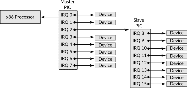
Figure 1: The Arrangement of Master and Slave PICs
Figure 1 shows this arrangement, as you can see, now, there are 15 slots in the whole system instead of only 8 slots. In the master PIC, the third slot (IRQ2) is connected to the slave PIC, that is, whatever interrupt received by slave PIC from the devices that are attached to it, will be sent to the master PIC through IRQ2. All other slots in both master (IRQ0 to IRQ7 but IRQ2) and slave PICs (IRQ8 to IRQ15) are connected to external devices. There is a standard which tells us the device type that each IRQ is dedicated to, for example, IRQ0 is the interrupt which is received by a device known as system timer which is a device that sends an interrupt in each unit of time which makes it extremely useful for multitasking environment as we shall see later when we start discussing process management, the following table shows the use of each IRQ 20.
| IRQ | Description |
|---|---|
| 0 | System Timer |
| 1 | Keyboard (PS/2 port) |
| 2 | Slave PIC |
| 3 | Serial Port 2 (COM) |
| 4 | Serial Port 1 (COM) |
| 5 | Parallel Port 3 or Sound Card |
| 6 | Floppy Disk Controller |
| 7 | Parallel Port 1 |
| 8 | Real-time Clock |
| 9 | APCI |
| 10 | Available |
| 11 | Available |
| 12 | Mouse (PS/2 port) |
| 13 | Coprocessor |
| 14 | Primary ATA |
| 15 | Secondary ATA |
After receiving an IRQ from a device, PIC should send this request to the processor, in this stage each IRQ number is mapped (or translated, if you prefer) to an interrupt number for the processor, for example, IRQ0 will be sent to the processor as interrupt number 8, IRQ1 will be mapped to interrupt number 9 and so on until IRQ7 which will be mapped to interrupt number 15d (0Fh), while IRQ8 till IRQ15 will be mapped to interrupts number from 112d (70h) to 119d (77h).
In the real-mode, this mapping will be fine, but in protected-mode it is going to cause conflicts between software and hardware interrupts, that is, one interrupt number will be used by both software and hardware which may causes some difficulties later in distinguishing the source of this interrupt, is it from the software or hardware? For example, in protected mode, interrupt number 8 which is used for system timer interrupt by PIC is also used by the processor when a software error known as double fault occurs. The good thing is that PIC is programmable, which means that we can send commands to PIC and tell it to change the default mapping (from IRQs to processor's interrupts number) to another mapping of our choice.
There are two well-known types of communicating with external devices by the processor, we have already encountered one of them when we worked with video memory which causes the processor to communicate with the screen to write characters or draw pixels, this type of communication from the processor to a devices is known as memory-mapped I/O communication, that is, the main memory is used to perform the communication.
There is another type which is used by PIC and this type is known as port-mapped I/O communication. In this method, each device (that uses this way) has ports, each port has its own unique number and job, for example, master PIC has two ports, the number of the first port is 20h while the number of the second port is 21h, the first port is used to send commands 21 to master PIC while the second port is used to write data on it so the master PIC can read it. The same is applicable to slave PIC with different port numbers, a0h and a1h respectively. PIC has no explicit command to remap IRQs, instead, there is a command to initialize PIC, this initialization consists of multiple steps and one of these steps it is to set the required mapping. Now, we can present the skeleton of setup_interrupts as following.
setup_interrupts:
    call remap_pic
    call load_idt

    ret
First, we are going to remap IRQs to different interrupt numbers by sending initialization command to both master and slave PICs, then we are going to initialize and load IDT and write the necessary interrupts handlers which are also known as interrupt service routines (ISRs).
3.3.1 Remapping PICs
As we have said, we need to change the default mapping between IRQs and interrupt number of the processor to make sure that there are no more than one source can emit a signal to one interrupt number, this process is known as PIC remapping which is simple to perform. As we knew, PIC is a port-mapped I/O, and by using out instruction of x86 we can write something on a given port number.
The initialization command of PIC is represented by the number 11h, which means writing this value on the command port of PIC by using out instruction is going to tell the PIC device that we are going to initialize it. When we send this command to the PIC through its own command port (20h for master PIC and a0h for slave PIC), it is going to wait for us to write four parameters on its data port (21h for master PIC and a1h for slave PIC), the values of these parameters are represented by numbers as we shall see in a moment.
The first parameter that should be provided to initialization command is the new starting offset of IRQs, for example, if the value of this parameter is 32d for master PIC, that means IRQ0 will be sent to the processor as interrupt number 32d instead of 8d (as in default mapping), IRQ1 will be sent to the processor as interrupt number 33d and so on. The second parameter tells the PIC (that we are initializing) in which of its slot the other PIC is connected. The third parameter tells the PIC which mode we would like it to run on, there are multiple modes for PIC devices, but the mode that we care about and need to use is x86 mode. The fourth parameter tells the PIC which IRQs to enable and which to disable. Now, let's see the code of remap_pic routine which implements what we have just described by setting the correct parameters to the initialization command of both master and slave PICs.
remap_pic:
    mov al, 11h

    send_init_cmd_to_pic_master:
        out 0x20, al

    send_init_cmd_to_pic_slave:
        out 0xa0, al

    ; ... ;

    make_irq_starts_from_intr_32_in_pic_master:
        mov al, 32d
        out 0x21, al

    make_irq_starts_from_intr_40_in_pic_slave:
        mov al, 40d
        out 0xa1, al

    ; ... ;

    tell_pic_master_where_pic_slave_is_connected:
        mov al, 04h
        out 0x21, al

    tell_pic_slave_where_pic_master_is_connected:
        mov al, 02h
        out 0xa1, al

    ; ... ;

    mov al, 01h

    tell_pic_master_the_arch_is_x86:
        out 0x21, al

    tell_pic_slave_the_arch_is_x86:
        out 0xa1, al

    ; ... ;

    mov al, 0h

    make_pic_master_enables_all_irqs:
        out 0x21, al

    make_pic_slave_enables_all_irqs:
        out 0xa1, al

    ; ... ;

    ret
Note that the labels here are optional, I've added them for the sake of readability, you can get rid of them if you want. As you can see, the command and data port for both master and slave PICs are used to send initialize command and the parameters. The instruction out can only take the register ax as second operand and due to that, the number that represent the command or the data that we would like to send are always set to al first which is used later as the second operand of out. Also, it should be obvious that the first operand of out is the port number, while the second operand is the value that we would like to send.

Figure 2: Master PIC's Data Format to Set The Place of Slave PIC
You may ask, why the value is 4 is used in the label tell_pic_master_where_pic_slave_is_connected 22 instead of 2 since we said earlier that the salve PIC is connected to master PIC through IRQ2. The reason of that is the format of the data that should be sent to master PIC in order to tell it the place where slave PIC is attached to. This format is shown in figure 2 which shows that the size of the data is 1 byte and each IRQ is represented by one bit, that is, each bit is used as a flag to indicate which IRQ we would like to use.

Figure 3: Slave PIC's Data Format to Set The Place of Master PIC
In our case, slave PIC is connected to master PIC through IRQ2 which is represented by bit 2, which means the value of this bit should be 1 and all other bits should be 0, this gives us the binary sequence 0000 0100 which is 4d. Assume that the slave PIC is connect to master PIC through IRQ7, then the binary sequence will be 1000 0000, which is 128d. For the slave PIC, the format is shown in figure 3 and as you can see, only bits 0 to 2 can be used while the others should be 0. By using these three bits we can represent the number 8 at most, the normal way of representing the numbers can be used here and for that the value 2 is passed to slave PIC to tell it that it is connected to master PIC through IRQ2 in the label tell_pic_slave_where_pic_master_is_connected.
3.3.2 Writing ISRs and Loading IDT
Right now, everything is ready to write the code of loading IDT and ISRs. The first one is too simple and similar to the code of loading the GDT table, the following is the code of load_idt routine.
load_idt:
    lidt [idtr - start]
    ret
As you can see, nothing is new here. The instruction lidt is used to load the content of the register idtr by using the same way that we have already used in the previous routine load_gdt. Now, for the sake of organizing, I'm going to dedicate a new file for the related stuff of IDT and ISRs and this file will be called idt.asm. In the end of starter.asm the following line should be added %include "idt.asm", exactly as we did with gdt.asm.
At least, we need to define 49 ISRs since the interrupts from 0 to 31 are used by the processor to indicate that some error happened in the system. In fact, interrupts 22 to 31 are reserved and has no use for us, but we need to fill their entries in the IDT table to be able to use the interrupts starting from 32. While the interrupts 32 to 48 are now used by PIC after the remapping for hardware interrupts (IRQs). Hence, we need to fill the entries of all of these interrupts in the IDT to make sure that our kernel runs correctly. Right now, we are going to use the same skeleton for the ISRs that we are going to define, let's start with isr_0 which is the name of the routine that handles interrupt 0. Starting from here, the code that are presented should be in the file idt.asm unless otherwise is mentioned explicitly.
isr_0:
    cli
    push 0
    jmp isr_basic
The code here is too simple, we first make sure that interrupts are disabled by using the instruction cli; in the time that we are handling an interrupt, we don't want another interrupt to occur, it will be more obvious why this is important when we start to implement process management in 539kernel.
After disabling the interrupts, we push to the stack the value 0 which is the number of the current interrupt, this pushed value can be used later by a C function that we are going to call as a parameter 23, in this way, we can have just one C function that works as an interrupt handler which receives a parameter that holds the interrupt number which should be handled. After pushing the interrupt number, the routine is going to jump to the label isr_basic which contains the basic code of all ISRs that we are going to define.
Now, for all other ISRs that are related to the processor, that is, from interrupt 1 to 31 we are going to use the exact same code, only two things should be changed, the name of the routine should indicate the interrupt number, for example isr_1 for interrupt 1, isr_2 for 2 and so on, the second change is the pushed value. I'm not going to show you all 31 ISRs in here since they need a lot of space, but you can always refer to 539kernel source code if the matter isn't clear for you and the following is an example of ISRs 1, 2 and 3. The label isr_basic will be defined later on.
isr_1:
    cli
    push 1
    jmp isr_basic

isr_2:
    cli
    push 2
    jmp isr_basic

isr_3:
    cli
    push 3
    jmp isr_basic
The second set of ISRs is the one that handles the IRQs and the interrupt numbers here, as we mentioned earlier, starts from 32 to 48. The following is an example of one of them which is isr_32.
isr_32:
    cli
    push 32
    jmp irq_basic
It's exactly the same code as the ISRs before 32, the only difference is the label that will the routine jumps to. In the current case it is irq_basic, which is the basic code for all interrupts that handles the IRQs, hence, isr_33 till isr_48 has the same code as isr_32 but with changing the pushed value. The following is the code of isr_basic.
isr_basic:
    call interrupt_handler

    pop eax

    sti
    iret
Simply, isr_basic calls a function known as interrupt_handler which is a C function that is going to be in the main kernel code, to make NASM able to know that this function is defined elsewhere than the assembly code, the line extern interrupt_handler should be added before start routine in starter.asm, exactly as we did with the function kernel_main.
After the function interrupt_handler returns, the stack of the current ISR is cleaned by eliminating the value that we have pushed which represents the number of the current interrupt, this is performed by using pop instruction which requires an operand to store the popped value on it and for no reason I've chosen eax. This is a simplest way of cleaning the stack's frame, another well known way is add esp, 4 where the second operand is the size of all data that we have pushed on the frame and we would like to eliminate before return, in our case, the size of the number that we have pushed is 4 bytes. As you can see, the latter method of cleaning the stack is more preferred since no place to store the popped value is needed and most probably you are going to encounter this method in the real codes much more. For the sake of simplicity, I'm going to keep the earlier method in the current case unless the other is needed.
Finally, the ISR re-enables the interrupts with the instruction sti and returns by using the instruction iret instead of the normal ret that we have used before, the former one is the one that should be used by interrupt handlers to return. The following is the code of irq_basic.
irq_basic:
    call interrupt_handler

    mov al, 0x20
    out 0x20, al

    cmp byte [esp], 40d
    jnge irq_basic_end

    mov al, 0xa0
    out 0x20, al

    irq_basic_end:
        pop eax

        sti
        iret
The fundamental functionality of irq_basic is same as isr_basic, it calls the C function interrupt_handler and in the end it cleans the stack and returns (in label irq_basic_end), the question now, what is this additional code between calling the C function and returning? As you know, IRQs come from one of the PICs of the system, and this PCI requires to be told that the IRQ it sent has been handled, to do that the PIC command known as end of interrupt (EOI) should be used and that's what the code does.
The command EOI should be sent to the master PIC after handling all IRQs (the ones that belong to the master and also the slave), but for the slave PIC this command should be sent only after the IRQs of slave PIC are handled, that is, interrupt number 40 till 48. So, after returning from the C function interrupt_handler, the command EOI is sent directly to the mater PIC. As you can see, we write the value 20h to the port 20h, the first value represents that EOI command, while the second value represents the command port of master PIC as we learned earlier. After that, the interrupt number, that we have pushed on the stack in the beginning of the ISR, is used to check if the interrupt that we have handled is greater than or equal 40d, if this is not the case, a jump is performed to irq_basic_end, otherwise, EOI command is sent to the slave PIC through its command port a0h.
Now, we are ready to define the IDT table, to not take too much space I will show only the first three entries, but the full table should have 49 entries, all of them with the same exact fields and the only difference is the label name of the ISR 24.
idt:
    dw isr_0, 8, 0x8e00, 0x0000
    dw isr_1, 8, 0x8e00, 0x0000
    dw isr_2, 8, 0x8e00, 0x0000
The meaning of the values of the fields are summarized in the following table.
| Handler's Name | Segment Selector | Present | Privilege Level | Descriptor Size | Gate Type |
|---|---|---|---|---|---|
| isr_0 | 8 (Kernel's Code) | Yes | 0 | 32-bit | Interrupt |
| isr_1 | 8 (Kernel's Code) | Yes | 0 | 32-bit | Interrupt |
| isr_2 | 8 (Kernel's Code) | Yes | 0 | 32-bit | Interrupt |
As in GDT table, I've written a Python script that let you manipulate the properties of descriptors by getting a human readable input, the code of the script is the following.
import json;

def generateIDTAsWords( idtAsJSON, nasmFormat = False ):
    idt = json.loads( idtAsJSON );
    idtAsWords = '';

    for entry in idt:
        if nasmFormat:
            idtAsWords += 'dw ';

        # ... #

        present = ( 1 if entry[ 'present' ] else 0 ) << 7;
        dpl = entry[ 'dpl' ] << 6;
        size = ( 1 if entry[ 'gate_descriptor_size' ] == '32-bit' else 0 ) << 3;
        gateType = ( 0 if entry[ 'interrupt_gate' ] else 1 );

        byteFive = present | dpl | ( 0 << 11 ) | size | ( 1 << 2 ) | ( 1 << 1 ) | gateType;

        wordThree = '0x' + format( byteFive, 'x' ).zfill( 2 ) + '00';

        # ... #

        idtAsWords += entry[ 'isr_routine_name' ] + ', ' + str( entry[ 'isr_segment_selector' ] ) + ', ' + wordThree + ', 0x0000'  + '\n';

    return idtAsWords;
The following is an example of using generateIDTAsWords.
idt = '''
[
    {   "isr_routine_name": "isr_0", "isr_segment_selector": 8, "present": true, "dpl": 0, "gate_descriptor_size": "32-bit", "interrupt_gate": true },
    {   "isr_routine_name": "isr_1", "isr_segment_selector": 8, "present": true, "dpl": 0, "gate_descriptor_size": "32-bit", "interrupt_gate": true }
]
''';

print( generateIDTAsWords( idt, True ) );
After defining the entries of IDT, we can define the label idtr which will be the value that we will load in the special register idtr.
idtr:
    idt_size_in_bytes   :   dw idtr - idt
    idt_base_address    :   dd idt
It should be easy to you now to know why idtr - idt gives us the size of IDT in bytes. Also, you should know that if the label idtr is not right below the label idt this will not work. I've used this method instead of hardcoding the size of the table 8 * 49 = 392 in the code to make sure that I don't forget to change the size field when I add a new entry in IDT, you are free to hardcode the size as we did in gdtr if you like to. Finally, the C function interrupt_handler can be defined in the end of main.c as following.
void interrupt_handler( int interrupt_number )
{
    println();
    print( "Interrupt Received " );
    printi( interrupt_number );
}
It simply receives the interrupt number as a parameter, as you have expected, and prints this number in an appealing way.
And now we have got the progenitor of 539kernel! Compiling and running this code is going to print the messages Welcome to 539kernel! then We are now in Protected-mode then 539 and finally, our first interrupt will be received and the message Interrupt Received 32 will be printed on the screen, this interrupt will not be received just once since it is the interrupt of the system timer the kernel will keep receiving it and prints the same message every given unit of time. We will use the system timer later when we start discussing the scheduling of processes in chapter .
3.4 Quick View of the Changes of Makefile
As you may have noticed, the Makefile of the progenitor version of 539kernel has some different aspects than the one that we have used in the bootloader version of 539kernel. The first difference is the way that we assemble starter.asm, as you can see, unlike bootstrap.asm, the output of the process of assembling the starter is an ELF32 binary file instead of flat binary file. As you know, the code of the starter is related to the C code of 539kernel, that is, there are C functions that are called in the starter code. To make the starter able to reach this C code correctly, the binary output of both starter.asm and main.c should be linked. It is the responsibility of the linker to generate a final binary file that understands what the starter mean when it calls the C function interrupt_handler for example. If the linking process between the two files is not performed, the starter will never know where is the code of interrupt_handler or kernel_main.
To link two binary files, they should have the same format and this format makes it possible to link the files that generated by using it. GCC generates ELF binary files by default, so, when we assemble starter.asm we tell NASM to generate and ELF file. After that the output binary files (AKA: object files) of both starter.asm and main.c are linked by using the command ld, we tell the linker that we are linking ELF object files, the order of the files that we pass to the linker to link is important, as you can see starter.o is passed before kernel.elf, which makes the linker puts the code of the starter before the code of the main kernel in the final output ELF binary file 539kernel.elf. Because ELF is not understandable by the machine unless some code interprets it, we convert it to a flat binary file by using the command objcopy, in this way, the bootloader can load the kernel without the need of dealing with the details of ELF format.
Also, you can see that the final image of the kernel kernel.img is generated by writing the content of bootloader first, then the kernel and then the image is fill with around 1MB of zeros, while this step isn't necessary for QEMU, but if you decide to use Bochs instead, such a step is required. While we are going to stick with the former one right now, the latter one, in my humble opinion, has better debugging tools.
Another important aspect of the new Makefile is the flags that are passed to GCC, we need to be careful with these flags and pass the correct ones to make sure that GCC compiles our kernel correctly since GCC compiles user-space applications by default. The flag -Wall tells GCC to show us the warnings on our code. The flag -m32 makes GCC generate 32-bit code. The flag -c stops the linker from running by default since we are going to run it later manually with specific options as you have seen. The flag -ffreestanding indicates that we are compiling a code that the standard library of C is not available for it and the main function is not necessary for it. Both flags -fno-asynchronous-unwind-tables and -fno-pie are used to eliminate some extra code that is generated by the GCC to handle some situations that are related to user-space code. This is a quick review of the functionality of the flags and you can always refer to the official documentation of GCC for more details.
3.5 A Traditionalist Implementer or a Kernelist?
Most probably you are objecting, "kernelist is not even a word!" I know, even my poor spell checker is shocked! Just bear with me a little bit and let me show you what I mean by the term kernelist.
In our journey of creating an operating system kernel we may ask ourselves, what is our role exactly? There are two possible roles that I would like to focus on, the first one is being a traditionalist implementer (for short: traditionalist). What I mean by the traditionalist is the one who writes the code of the kernel without focusing too much on the design of the kernel and the philosophical questions about that kernel, examples of these questions are "What is the problem that the kernel will solve?", "How to design its architecture to accomplish its goal" and so on, also the traditionalist tends to implement already well-known solutions that have been used many years with no or little changes. The kernelist, on the other hand, is the person who takes care of the questions about kernel's design and the new solutions for the problems and tries to answer these questions and presents a suitable kernel's design and solutions for specific problems. For example, writing a Unix-like kernel is the job of traditionalist, since the architecture of Unix is already designed by kernelists to solve specific problems.
Our goal from this book is to learn how to write an operating system kernel with a traditional design and no new ideas, so, we are taking the role of a traditionalist, the design of 539kernel is too simple and it solves no specific problem in a novel way, instead it uses the concepts that are already there and used by many operating systems as you will see in the next chapters, also it doesn't focus on some new problem to solve nor a new solution for an old problem, this makes 539kernel a working kernel that solves the same problems that other kernels solve by using the same methods that other kernels use, the advantage of this design is making 539kernel easy to implement which means it is a good starting point to learn about operating system kernels and that's the goal of this book.
The natural question for someone, who would like to continue in the journey of operating system kernels, to ask herself after implementing a basic kernel, "What's next?" and here where a kernelist is born! In fact, there are many real world problems in computing that need to be solved, also, there are many innovative ideas that need to be created, furthermore, there are many good ideas that have been presented by someone else but need to be realized in the real world systems, a lot of aforementioned can be found in the scientific papers 25.
The kernelist doesn't necessarily innovate new solutions by himself, but he can use modern solutions that have been proposed by other kernelist to implement and design a kernel with modern innovative and useful ideas instead of reimplementing the traditional solutions that have been with us for 60 years over and over again.
After reading this book to learn about creating a kernel and you would like to continue the journey, I encourage you to consider the role of kernelist. Using what you have learned to solve real-world problem is a good idea, and the world needs this kind of orientation. Although this is a book of traditionalist more that a kernelist, I've dedicated chapter for those who would like to, at least, take a look on being kernelist.
The script is based on the one which is provided in "JamesM's kernel development tutorials" (http://www.jamesmolloy.co.uk/tutorial_html/1.-Environment%20setup.html)↩
The term routine is more general than the terms function or procedure, if you haven't encounter programming languages that make distinctions between the two terms (e.g. Pascal) then you can consider the term routine as a synonym of the term function in our discussion.↩
As you know from our previous examination, the value of
cswill be changed by the processor once a far jump is performed.↩That's exactly what we have done with bootloader, refer back to chapter and you can see that we have passed the argument
-f bintoNASM.↩A symbol is a term that means a function name or a variable name.↩
In fact,
clidisables only maskable interrupts, as mentioned before, but I use the general term interrupts here for the sake of simplicity.↩The values of the descriptors here are used from Basekernel project (https://github.com/dthain/basekernel).↩
Otherwise it is going to be a paradox! to reach the
GDTtable you will need to reach theGDTtable first!↩Also, can be considered as true for
1and false for0.↩Boolean operators are well-known in programming languages and they are used mainly with
ifstatement.↩We use the relaxed definition of segment selector here that we have defined in the previous chapter .↩
A monochrome text mode is also available and its video memory starts from
b0000h.↩Thanks God!↩
As you know, in even locations of the video memory the character are stored, while in odd locations the color information of those characters are stored.↩
Can you tell why?↩
Please note that the way of writing this code and any other code in 539kernel, as mentioned in the introduction of this book, focuses on the simplicity and readability of the code instead of efficiency in term of anything. Therefore, there is absolutely better ways of writing this code and any other code in term of performance or space efficiency↩
The operation which is represented by % is known as modulus, in other words, the remaining value of a division.↩
Sorry for that! I, myself, think this is an interesting topic, but this book is about operating systems kernels!↩
The newer technology is known as advanced programmable interrupt controller (APIC)↩
Source: https://en.wikipedia.org/wiki/Interrupt_request_(PC_architecture)↩
Each device has its own set of commands.↩
I just realized that this is a really long name! Sorry, sometimes I become a readability freak!↩
That's possible due to the calling convention as we have discussed earlier in the previous chapter .↩
The values of the properties here are used from Basekernel project (https://github.com/dthain/basekernel).↩
In fact, I've started a project that generalize this thought and I called it
ResearchCoders. If you are interested in finding and implementing new ideas that solve real-world problems you may would like to check the website of the project (https://researchcoders.dev)↩